August. 25, 2026
When I troubleshoot valve limit switch problems, I follow the signal from the moving valve to the actuator, switch contacts, wiring, terminal block, and PLC input. How can I troubleshoot issues with valve limit switches in my machinery? I begin by isolating electrical, pneumatic, hydraulic, and mechanical energy, then verify valve travel before testing the switch. This sequence prevents me from replacing a functional switch when the actual fault is caused by poor alignment, inadequate air pressure, a failed solenoid, damaged wiring, or an incorrect control input.
A valve limit switch is an electromechanical device that reports the position of a valve or actuator to a control system. On a quarter-turn pneumatic actuator, the switch is commonly connected to a shaft, cam, lever, or position indicator that changes the electrical contact state as the actuator rotates. On linear valve assemblies, a plunger, roller lever, or cam mechanism may respond to the stem position.
In a typical control circuit, the switch contains a common terminal, a normally open contact, and a normally closed contact. When the actuator reaches a defined position, the internal mechanism transfers the contact state, allowing the PLC, relay, indicator, or interlock circuit to recognize that the valve is open or closed. The switch does not normally control the valve movement by itself; it provides feedback about the result of that movement.
I use valve limit switches because visual indicators alone cannot confirm that the control system has received the correct position signal. A valve may appear closed while the actuator has stopped short, or the actuator may reach its mechanical stop while the electrical contact remains open because the cam is misadjusted. Position feedback is therefore important for sequencing, alarm handling, permissive logic, and protection against starting a process in an unsafe condition.
A limit switch differs from a proximity sensor because the limit switch uses physical movement, while a proximity sensor detects a target without direct contact. A proximity sensor can reduce mechanical wear, but it requires correct sensing distance, target material, supply voltage, and signal compatibility. I select between these technologies according to actuator design, contamination, vibration, required switching frequency, available space, and the control system’s input type.
!
Before beginning valve limit switch troubleshooting, I collect the electrical drawings, pneumatic or hydraulic schematics, actuator data, switch model, PLC input description, and the valve’s normal operating sequence. I also record whether the fault occurs during opening, closing, both directions, startup, or only after the machine has operated for several hours. This information helps separate a mechanical travel problem from an intermittent electrical problem.
My basic test equipment includes a calibrated digital multimeter, insulated test leads, a non-contact voltage detector where appropriate, screwdrivers, torque tools, terminal labels, cleaning materials approved for the enclosure, and a portable 24 VDC test supply if the maintenance procedure permits it. For pneumatic valve position feedback troubleshooting, I also need a pressure gauge or access to the machine’s regulated air-pressure indication. I never assume that the nominal control voltage is 24 VDC; I verify the drawing and measure the actual circuit.
I establish the normal state of every relevant signal before disconnecting anything. For example, I may record the commanded state, actual valve position, open feedback, closed feedback, solenoid output, air pressure, and PLC input LED in a table. A documented starting condition prevents confusion when a temporary test changes the machine state.
The most reliable method is to trace the complete signal path in order rather than testing random components. I check the physical movement first, then the switch mechanism, then the electrical contacts, then the field wiring, and finally the control-system input. If the valve cannot reach its end position, electrical adjustment alone will not correct the fault.
I first place the machinery in the approved maintenance state and apply the site’s lockout/tagout procedure. Depending on the installation, this may require isolating motor power, control power, compressed air, hydraulic pressure, gravity loads, spring force, and process pressure. I verify zero energy using the required test method instead of relying only on a closed disconnect or an HMI status message.
I then define the fault in measurable terms. “Valve limit switch failed” is not enough information for a maintenance record, so I write a statement such as: “Valve commanded closed, actuator reached approximately 90 degrees, closed feedback remains off, and PLC input voltage measures 0.2 VDC.” A statement with position, command, feedback, and measured voltage gives the next technician a usable diagnostic reference.
I do not bypass a limit switch, install a jumper, or force a PLC input unless the approved procedure specifically allows it and the risk assessment covers the test. A jumper can remove an interlock while the valve remains in the wrong position, and manually stroking a valve can release stored pressure or expose personnel to moving linkage. If process isolation cannot be verified, I stop the test and escalate it to the responsible engineer or authorized maintenance supervisor.
Next, I check whether the valve itself can travel from fully closed to fully open. I inspect the actuator coupling, mounting bracket, shaft connection, valve stem, mechanical stops, linkage, and position indicator for looseness or displacement. On a pneumatic actuator, I verify that the solenoid valve energizes, the air supply reaches the actuator, and the pressure remains within the actuator manufacturer’s operating range.
A valve that moves slowly, stalls, overshoots, or stops before its end position can produce an apparent limit switch fault. Common causes include inadequate air pressure, blocked exhaust flow controls, a damaged diaphragm, seized valve packing, incorrect actuator sizing, foreign material in the valve, or a misadjusted mechanical stop. I compare actual movement with the expected travel, such as a quarter-turn actuator rotating approximately 90 degrees, but I use the equipment documentation as the controlling reference.
I also observe whether the actuator moves in the correct direction. If the open and closed signals are reversed, the problem may be incorrect actuator orientation, swapped switch wiring, reversed cam settings, or a control logic error. I record the physical position separately from the electrical indication because a green HMI symbol does not prove that the valve is mechanically open.
For the visual and mechanical inspection, I examine the limit switch housing, cover, cable entry, mounting screws, actuator shaft, cams, rollers, levers, plungers, and position indicator. I look for cracked housings, missing covers, loose hardware, bent levers, worn rollers, damaged seals, water entry, oil residue, dust, metal particles, and corrosion on the terminals. A small amount of contamination can increase contact resistance or prevent a plunger from returning fully.
The switch must be mounted so the actuator reaches the intended contact position without forcing the mechanism beyond its rated travel. I check whether the cam engages the switch too early, too late, or at an excessive angle. If the actuator continues pushing after the contact changes, the mechanism may experience unnecessary impact, which can produce intermittent feedback and shorten service life.
I gently operate the switch by hand only when the machine is in a safe, de-energized state and the manufacturer’s procedure permits it. The actuator should move smoothly, return to its original position, and produce a clear change in contact state. A sticky plunger, weak return spring, inconsistent click, or lever that does not return completely indicates a mechanical defect rather than a wiring issue.
Actuator limit switch adjustment should begin with the valve positioned at a verified mechanical endpoint, not with the electrical indicator alone. I place the valve fully closed according to the process and actuator documentation, loosen the cam or adjustment hardware, and set the closed-position contact so it changes state near the intended endpoint. I then repeat the process with the valve fully open.
I avoid setting the switch exactly at the point where the actuator reaches its hard stop. Instead, I follow the equipment manufacturer’s specified allowance so the contact changes reliably without using the switch as a mechanical stop. If the switch is adjusted too close to the stop, thermal expansion, vibration, coupling backlash, or small changes in actuator travel can cause signal chatter.
After adjusting one cam, I cycle the actuator several times and verify both directions. I check the fully closed signal, fully open signal, and any intermediate feedback used by the control system. For a valve with two discrete switches, I confirm that the open and closed contacts cannot both indicate the final position at the same time unless the control logic intentionally allows a transition state.
A practical calibration record includes the valve tag, actuator model, switch model, closed travel position, open travel position, cam setting, contact state, PLC input state, and cycle-test result. I normally perform at least three open-close cycles after adjustment and record whether the signal changes at the same point each time. If the signal changes at different positions across repeated cycles, I investigate backlash, loose couplings, worn cams, or actuator instability.
To understand how to test a valve limit switch with a multimeter, I begin by isolating the switch from the control circuit when possible. Testing resistance while the switch remains connected to a PLC input, relay coil, suppression device, or parallel circuit can produce a misleading reading. I identify the common, normally open, and normally closed terminals from the wiring diagram or the switch markings.
With the meter set to continuity or low resistance, I place one probe on common and the other on the normally closed terminal. In the unactuated state, I typically expect continuity, often close to 0 ohms, although the exact value depends on the meter and contact condition. When I actuate the switch, that path should open and display an overload or open-circuit indication, commonly shown as “OL.”
I then test common to normally open. The unactuated state should normally show an open circuit, while the actuated state should show continuity close to 0 ohms. If both circuits remain open, the internal contact mechanism may be damaged; if both remain closed, the switch may be welded, incorrectly identified, or incorrectly connected.
| Multimeter result | Likely interpretation | Next check |
|---|---|---|
| COM–NC remains near 0 Ω in both states | NC contact is stuck or terminals are misidentified | Confirm terminal markings and replace if confirmed |
| COM–NO remains OL in both states | NO contact is not closing or actuator is not reaching the mechanism | Manually test the switch, then check actuator travel |
| Resistance changes but exceeds several ohms | Dirty, worn, burned, or corroded contacts | Inspect contact condition and measure under the actual circuit |
| Signal changes only when the lever is pressed sideways | Mechanical alignment or mounting problem | Correct bracket, cam, or actuator alignment |
| Continuity is correct disconnected but wrong when connected | External wiring, load, or PLC circuit problem | Test voltage drop and field wiring |
| Reading changes intermittently during steady actuation | Contact bounce, vibration, loose terminal, or worn mechanism | Repeat while moving cable and inspect mounting |
I also perform a voltage test with the circuit energized only when the approved procedure allows live measurement. I measure the supply at the switch, the voltage across the contact, and the voltage arriving at the PLC input. For a nominal 24 VDC circuit, a measurement near 24 VDC at the supply but near 0 VDC at the PLC input points toward an open conductor, terminal, fuse, relay, or contact path.
The exact acceptable voltage depends on the PLC input specification, but I compare the measured value with its defined ON and OFF thresholds. A 24 VDC input that reads 24.1 VDC at the terminal block but only 5 VDC at the PLC suggests voltage drop or a wiring fault. A supply reading of 18 VDC may indicate a power-supply problem, excessive load, poor connection, or incorrect circuit design rather than a bad limit switch.
Once the switch contact test is complete, I trace the signal through every connection point. I inspect the switch terminals, cable gland, junction box, terminal block, marshalling panel, relay interface, input fuse, and PLC terminal. Loose ferrules, broken conductors inside flexible cable, damaged insulation, incorrect terminal numbers, and corrosion can all create intermittent feedback.
I perform a continuity test from the switch terminal to the PLC input only after isolating both ends of the conductor. A conductor that measures near 0 ohms with no movement may still fail when the cable flexes, so I repeat the test while gently moving the cable at the actuator, gland, junction box, and cabinet entry. If the resistance changes during movement, I treat the cable or termination as defective.
The signal-path decision tree is straightforward:
A valve that will not open or close may have a limit switch problem, but it may also have a command-side failure. I check whether the PLC output energizes the solenoid coil, whether the coil draws the expected current, and whether the directional valve shifts. I also verify that the actuator receives sufficient air pressure during the movement command rather than only when the system is idle.
If the solenoid receives its rated voltage but the actuator does not move, I inspect the coil, spool, exhaust muffler, air tubing, regulator, and actuator. If the solenoid receives no voltage, I trace the PLC output, safety permissives, interlocks, fuses, relay contacts, and control logic. The limit switch can report that the valve did not move, but it may not be the reason movement failed.
I compare the command status and feedback status in all combinations. For example, “open command on, open feedback off” indicates incomplete travel, switch adjustment, wiring, or a timeout condition, while “open command off, open feedback on” may indicate a stuck actuator, welded contact, or incorrect logic. A PLC input that changes electrically but not logically requires a software or input-configuration review, not immediate hardware replacement.
I use the following valve limit switch troubleshooting checklist during maintenance calls and planned inspections. It is structured to connect the symptom with the physical position, command state, feedback state, measured value, and corrective action. The record should remain with the machine history rather than being discarded after the repair.
The most common failures I see are misalignment, loose mounting, contaminated contacts, damaged cables, worn actuator mechanisms, incorrect NO/NC wiring, and incomplete valve travel. These faults often produce similar symptoms, so replacing the switch based only on an HMI alarm can create unnecessary cost. I use the measured signal path to identify the actual failure location.
| Symptom | Possible cause | Diagnostic confirmation | Corrective action |
|---|---|---|---|
| Valve moves but no position feedback appears | Wrong cam setting, open contact, broken wire | Contact changes at switch but voltage is absent at PLC | Adjust, repair wiring, or replace switch |
| Closed feedback remains on while valve opens | Stuck NC contact or incorrect wiring | COM–NC does not change state | Correct wiring or replace switch |
| Open and closed signals appear together | Cam overlap, short circuit, PLC logic issue | Measure both inputs during transition | Separate adjustment and inspect logic |
| Feedback flickers during operation | Vibration, contact bounce, loose terminal | Signal changes without stable movement | Tighten, realign, replace worn mechanism |
| Valve fails to move at all | Solenoid, air pressure, interlock, actuator fault | No actuator movement despite command | Repair command or pneumatic circuit |
| Feedback is correct locally but wrong on HMI | PLC tag or logic mapping error | PLC input changes while display does not | Correct programming or input mapping |
| Fault occurs only after washing or outdoor exposure | Moisture ingress or corrosion | Inspect enclosure and measure insulation | Improve sealing and replace damaged parts |
I repair a valve limit switch when the internal contacts test correctly, the housing is intact, the actuator mechanism moves freely, and the fault is limited to alignment, mounting, terminal tightening, or wiring. A repair should be followed by repeated operation, not just a single continuity check. I also document the original fault and the final measured values.
I replace the switch when the contacts remain stuck, resistance is unstable, the return mechanism is weak, the housing or seal is damaged, the terminals are burned, or the device cannot maintain calibration through repeated cycles. Replacement is also appropriate when the switch’s electrical rating, environmental protection, actuator style, or contact configuration does not match the machinery. Installing a physically similar switch with a different contact rating can create a new control failure.
For total cost of ownership, I compare the component price with labor, downtime, access requirements, and the probability of repeat failure. An illustrative calculation might include a $60 switch, $120 in technician labor, and $300 in production interruption, producing a $480 immediate event cost. Spending an additional $40 on the correctly rated replacement may be financially preferable if it prevents a second service call, but the decision should be based on documented failure history rather than assumptions.
When I evaluate a Limit Switch Supplier, I compare more than unit price. I check contact configuration, actuator type, operating environment, mounting dimensions, electrical ratings, documentation, inspection records, warranty terms, customization capability, and expected delivery time. A low purchase price does not reduce total cost if the replacement requires bracket modification, causes wiring changes, or arrives without the required technical data.
kacon presents industrial limit switch categories that include standard, safety, small, and customized solutions, with product examples using plunger, roller, cross-roller, ball-plunger, and adjustable roller-lever configurations. The company states that it has production bases in Incheon, Yueqing, and Weihai, and describes incoming-material checks, in-process inspection, packing checks, and final inspection within an ISO 9001 quality-management system. I would still request the exact datasheet, contact rating, protection level, dimensional drawing, test record, lead time, and replacement warranty for the specific valve application before approving a purchase.
For delivery risk management, I ask the supplier to confirm whether the model is standard stock, made to order, or customized. I also request a first-article approval process when the switch changes dimensions, actuator configuration, connector type, or contact arrangement. For critical machinery, I maintain at least one tested spare and record its part number, terminal layout, adjustment method, and approved substitute status.
After correcting the fault, I restore covers, cable glands, guards, air connections, and fasteners before returning the machine to service. I remove temporary test leads, verify that no jumper remains installed, and confirm that the switch wiring matches the drawing. I then conduct a controlled open-close test under the approved operating procedure.
My final report includes the original symptom, actual valve position, command status, feedback status, measured supply voltage, NO/NC resistance readings, PLC input voltage, actuator pressure, adjustment performed, parts replaced, cycle-test count, and technician name. This information creates a fault history that can reveal repeated alignment drift, water ingress, cable fatigue, or premature contact wear. A structured record is more useful than a simple note stating “limit switch changed.”
I also add the switch to a preventive-maintenance schedule based on operating conditions. A dusty, wet, vibrating installation may require more frequent inspection than a protected control cabinet, but the interval should be based on observed failure patterns and the manufacturer’s instructions. During each inspection, I verify mounting torque, enclosure condition, cable strain relief, actuator travel, signal transition, and PLC indication.
How can I troubleshoot issues with valve limit switches in my machinery? I use a safety-first sequence: isolate energy, verify valve and actuator movement, inspect the switch and alignment, test NO and NC contacts with a multimeter, trace wiring to the PLC, and confirm the complete command-to-feedback sequence. This method distinguishes mechanical faults from electrical contact failures, wiring defects, solenoid problems, inadequate air pressure, and PLC input errors.
I do not bypass a switch as a substitute for diagnosis, and I do not adjust cams until the valve’s fully open and fully closed positions are independently verified. I record measured resistance, voltage, actuator pressure, valve position, command status, and feedback status so the corrective action can be checked and repeated. When the switch has damaged contacts, unstable resistance, worn mechanics, or incompatible ratings, replacement through a documented supplier evaluation is safer and usually reduces repeat maintenance cost.
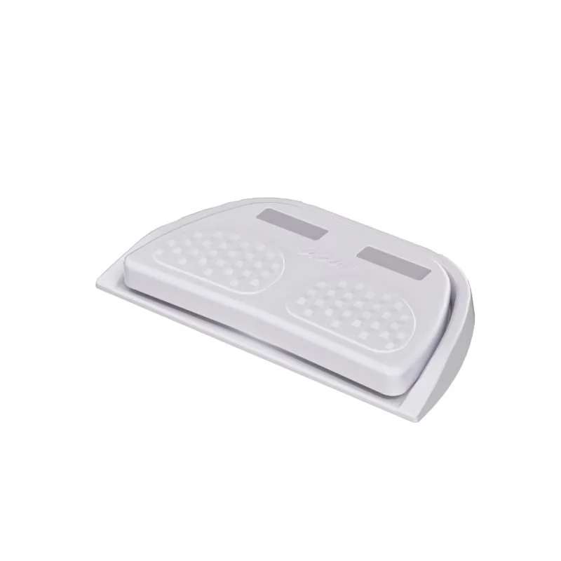 Momentary vs maintained foot switch
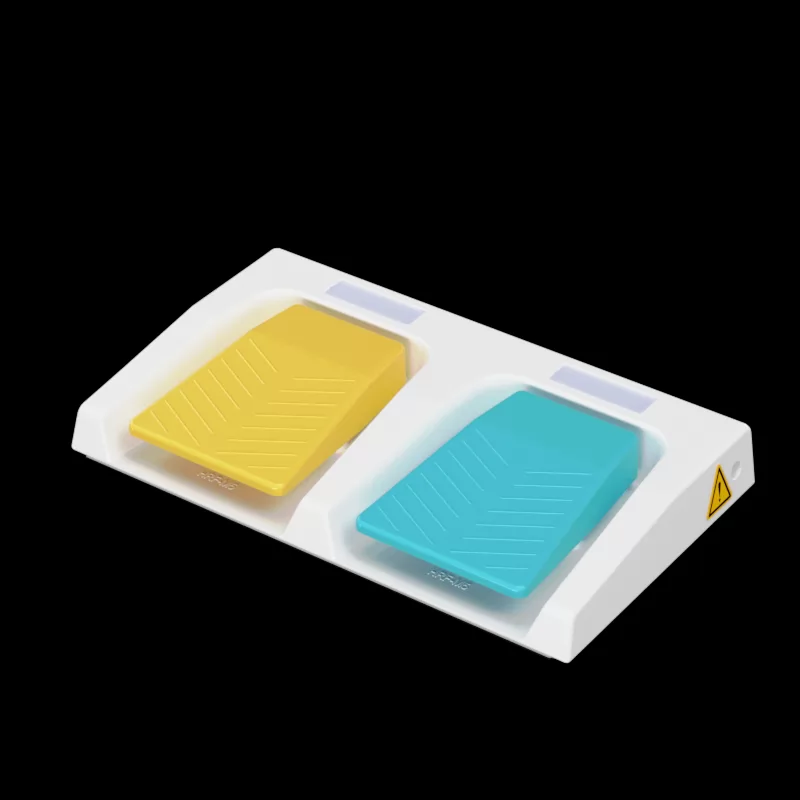 Ergonomic benefits of dual pedal design
 IP67 vs IP68 foot switch for marine use
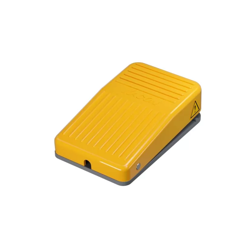 Best dual foot switch for hydraulic presses
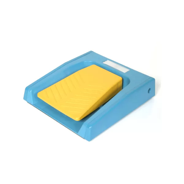 Wiring diagram for dual safety foot switches
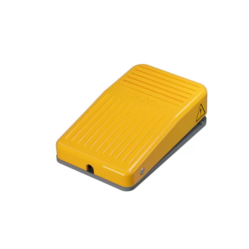 Troubleshooting 3-position switch contacts