August. 24, 2026
A CS-7 limit switch fault usually means the monitored mechanism is not producing the expected open or closed signal. When I troubleshoot one, I follow this order: isolate power, inspect the actuator and mounting, check wiring and terminals, perform a continuity test, then verify that the controller receives the correct input. I replace the switch only after separating a mechanical fault from a wiring, power-supply, input-module, or connected-equipment problem.
The designation “CS-7” is not sufficient by itself to establish the contact arrangement, voltage rating, actuator type, or reset method. Different manufacturers and equipment platforms may use CS-7 as a model or component reference, including industrial pneumatic sensing applications and clinical equipment interlocks. I therefore begin with the switch label, equipment nameplate, wiring diagram, and CS-7 limit switch manual before applying test voltage or ordering a replacement.
!
A limit switch is an electrically operated position sensor that changes contact state when a machine part, cylinder, door, cover, carriage, or actuator reaches a defined location. In a conventional mechanical design, a plunger, roller lever, or adjustable arm moves an internal contact block. In a magnetic sensing design, a magnet on a moving piston or component changes the state of a sensor mounted nearby.
The normal operating state depends on the equipment design. A normally open contact has no continuity when the actuator is released and continuity when the specified position is reached. A normally closed contact has continuity when released and opens when the actuator is operated, which is common in fail-safe monitoring circuits because a broken wire can also appear as a fault.
I do not assume that the switch should always be open or always closed. The correct state must be verified against the terminal labels, machine schematic, and controller logic. A switch that appears faulty during a static test may be operating correctly if the machine is holding the actuator in the opposite position or if the controller uses an inverted input.
The safest CS-7 limit switch troubleshooting procedure separates physical movement, electrical contact operation, and controller interpretation. I use the following sequence rather than immediately installing a jumper or replacing the component. This reduces the chance of damaging an input module or misidentifying the fault.
First, I photograph the switch label, terminal markings, connector orientation, actuator position, and surrounding wiring. I record the equipment model, fault code, operating cycle, and the exact point at which the fault appears. This information is especially important for CS-7 limit switch troubleshooting on furnace systems, automation equipment, pneumatic cylinders, and clinical equipment.
Next, I locate the applicable wiring diagram and identify:
If the switch has a three-terminal contact block, the terminals may be marked COM, NO, and NC. If it is a two-wire magnetic sensor, the circuit may instead depend on a supply, load, or electronic output. I never use a generic pinout when the equipment schematic is available.
A terminal-state error can produce the same symptom as a failed switch. For example, measuring COM-to-NO when the circuit actually uses COM-to-NC will show the opposite result without any component defect. Correct identification also prevents applying a multimeter’s resistance function to a powered circuit.
Before opening a panel or disconnecting terminals, I apply the equipment’s lockout and tagout procedure. I isolate all relevant energy sources, including mains power, control voltage, pneumatic pressure, hydraulic pressure, stored spring force, elevated mechanisms, and thermal energy. On furnace or clinical equipment, I also follow the service procedure for residual heat, radiation-related systems, or stored motion.
With power isolated, I inspect the actuator for bent metal, cracked plastic, loose fasteners, contamination, corrosion, and excessive wear. I manually move the mechanism through its normal travel only when the equipment procedure permits it. The actuator should move without binding and should reach the switch at the intended position rather than bottoming out against the switch housing.
I check whether the actuator fully releases after operation. A limit switch that remains pressed can stay electrically open or closed even though the machine has returned to its home position. A switch that is contacted too early may report “reached” before the mechanism is safely in position, while a switch contacted too late may cause a controller timeout.
| Inspection item | Normal observation | Fault indication |
|---|---|---|
| Mounting screws | Tight, with no visible movement | Switch shifts during operation |
| Actuator travel | Smooth and repeatable | Sticking, excessive force, or incomplete travel |
| Contact point | Mechanism meets actuator centrally | Side loading or impact at an angle |
| Release action | Actuator returns fully | Plunger or lever remains depressed |
| Alignment | Same position on repeated cycles | Contact point changes with vibration |
| Environment | Within rated temperature and enclosure conditions | Heat, moisture, dust, oil, or corrosion |
kacon operates as a Limit Switch Supplier with mechanical limit switch families that include different actuator configurations and enclosure options. That does not make every kacon model a direct CS-7 replacement. I use supplier information to compare actuator style, contact configuration, protection rating, certifications, and mounting dimensions, then verify compatibility with the original equipment documentation.
For a CS-7 limit switch wiring diagram, I trace each conductor from the switch to the terminal block, relay, input module, or controller. I look for loose screws, damaged insulation, pulled cable glands, bent connector pins, oxidation, crushed cable sections, and conductors that have fractured inside the insulation. I also compare the installed wiring with the documented schematic rather than relying on wire color.
When power remains isolated, I check terminal tightness and connector retention. A terminal can look connected while failing under vibration because the conductor is only partially clamped. For plug-in connectors, I inspect the locking tab and check whether the pin is recessed, pushed backward, or contaminated.
If the circuit passes through a relay, safety module, fuse, or terminal board, I include each point in the inspection. A switch may show correct continuity at its housing while the controller sees no signal because of an open conductor downstream. On long cable runs, I also consider shield grounding, cable routing near motor conductors, and induced electrical noise.
| Symptom | Likely wiring cause | Confirmation method |
|---|---|---|
| No input at controller | Open conductor or disconnected terminal | Continuity test from switch terminal to input terminal |
| Intermittent fault | Broken conductor, vibration, loose connector | Wiggle and flex test with power isolated |
| Permanent active signal | Shorted conductor or wrong terminal | Compare terminal-to-terminal resistance |
| Signal present but wrong logic | NO/NC misconnection or inverted input | Compare schematic with controller configuration |
| Fuse opens | Short to ground or overloaded circuit | Insulation and resistance checks with circuit isolated |
| Fault after washing or condensation | Moisture ingress or corrosion | Visual inspection and insulation evaluation |
I avoid probing live terminals with uninsulated tools. If a powered measurement is necessary, it should be performed by a qualified technician using insulated probes, a meter rated for the circuit category, and the equipment’s approved test procedure.
To perform a CS-7 limit switch continuity test, I first disconnect at least one switch lead from the circuit. Testing while the switch remains connected can produce false readings through relays, PLC inputs, lamps, coils, or parallel branches. I set the multimeter to resistance or continuity mode and verify the meter by touching the probes together.
I measure the expected contact pair in the released position, then operate the actuator and repeat the measurement. For a mechanical contact, a closed reading should generally be close to zero ohms after accounting for the test-lead resistance. An open reading should show the meter’s over-range indication or a very high resistance, often above 1 megohm on a meter with that range.
These are practical diagnostic values, not a substitute for the manufacturer’s specification. A contact reading of 2 to 5 ohms that changes when the cable moves may indicate contamination, contact wear, or a loose connection. A switch that changes state but does so inconsistently should not be accepted as serviceable merely because it produces continuity once.
I isolate power, disconnect one switch lead, identify COM, NO, and NC from the diagram, and measure resistance in both released and actuated positions. COM-to-NC should normally show continuity when released and open when actuated, while COM-to-NO should normally show the reverse. I repeat the test at least five times and gently move the actuator and cable; any unexplained state change, resistance above the specified contact value, or failure to switch indicates a mechanical, contact, or wiring problem.
| Test position | Terminal pair | Expected result | Measured result | Interpretation |
|---|---|---|---|---|
| Actuator released | COM-NC | Closed or specified resistance | ____ Ω | Pass/fail |
| Actuator released | COM-NO | Open or high resistance | ____ Ω | Pass/fail |
| Actuator operated | COM-NC | Open or high resistance | ____ Ω | Pass/fail |
| Actuator operated | COM-NO | Closed or specified resistance | ____ Ω | Pass/fail |
| Repeated cycling | Selected pair | Same result each cycle | ____ | Stable/intermittent |
For a two-wire electronic or magnetic CS-7 sensor, continuity mode may not provide a meaningful diagnosis. The device may require a defined supply voltage and may use a solid-state output rather than a dry contact. In that case, I use the model’s electrical diagram and measure supply, output, and load conditions without exceeding the stated voltage or current limits.
After the isolated tests are complete, I restore power only under the approved service procedure. I measure the voltage at the switch supply or contact circuit, then compare it with the equipment documentation. A missing supply voltage means the switch cannot be blamed until the fuse, power supply, relay, safety module, or upstream control circuit has been checked.
I then measure the signal at the controller input in both switch states. The input should change from its inactive level to its active level when the actuator operates. Depending on the system, this may be 0 V and 24 V DC, a different control voltage, or a contact signal referenced through a relay.
Indicator lights and error codes provide useful evidence but are not conclusive by themselves. A controller input LED that remains off may indicate an open switch, broken conductor, missing common reference, failed input channel, or incorrect logic configuration. I compare the voltage directly at the switch with the voltage at the controller terminal to locate where the signal disappears.
The switch is the likely fault when its actuator does not move correctly, its contact resistance is outside specification, or its state fails during repeated isolated tests. The wiring is more likely when the switch changes correctly at its terminals but the same state is absent at the controller input. The input module or control board becomes more likely when the correct voltage and signal arrive at the input terminal but the controller continues to display an incorrect state.
I use this decision sequence:
Does the mechanism reach the actuator?
If no, correct alignment, travel, obstruction, or equipment movement first.
Does the switch change state electrically?
If no, inspect the switch, actuator, and contact mechanism.
Does the state reach the controller terminal?
If no, trace the cable, connector, fuse, relay, and terminal block.
Does the controller recognize the state?
If no, evaluate input configuration, reference voltage, input channel, and control-board condition.
Does the machine still fault with a verified input?
If yes, investigate the connected equipment, sequence logic, timing, temperature, pressure, or other interlock.
This method prevents an unnecessary CS-7 limit switch replacement when the actual issue is a failed controller input or an equipment condition that correctly causes the switch to open.
A CS-7 limit switch that stays open may have a damaged contact, an actuator that never reaches its operating point, an open wire, or a controller that expects the opposite contact. I check the switch at the terminals first, then check the same circuit at the controller. If the switch is closed at its housing but open at the controller, the fault is downstream.
A switch that stays closed can be stuck mechanically, incorrectly adjusted, shorted by wiring, or connected to the wrong terminals. On a normally closed safety circuit, a permanently closed reading should be tested with the actuator both released and operated. If the contact never opens when the actuator is fully engaged, the switch or adjustment is suspect.
An intermittent limit switch fault requires more than one continuity reading. I cycle the mechanism repeatedly, inspect for vibration, move the cable at fixed points, observe connector movement, and record whether the failure occurs at a specific travel position or temperature. If the fault appears only during machine vibration, I inspect mounting rigidity, cable strain relief, actuator side loading, and contact repeatability.
Repeated trips may be caused by the switch, but they may also be the intended response to overheating, excessive travel, blocked airflow, pressure loss, door movement, or a timing error. For a furnace safety limit switch, I check airflow, filters, blower operation, temperature rise, and the manufacturer’s trip conditions before replacing the switch. For a clinical equipment interlock, I follow the authorized service manual and do not return the equipment to patient use until the safety circuit has been verified.
I do not recommend bypassing a safety circuit with a permanent jumper or leaving a jumper installed after testing. A limit switch may prevent motion into a hazardous position, interrupt heating, detect a guard opening, or confirm that a clinical component is correctly seated. Bypassing it can remove the protection while making the machine appear operational.
If an authorized service procedure allows a temporary simulation, the test must be controlled, documented, supervised, and removed immediately after the measurement. The technician should use the equipment’s approved test connector, simulator, or diagnostic mode when available. If no safe method is documented, I stop and escalate the issue rather than defeat the interlock.
I consider repair only when the defect is external and permitted by the equipment manufacturer, such as correcting actuator alignment, tightening a terminal, replacing a damaged cable section, or restoring a loose mounting bracket. I do not open a sealed switch, reshape a safety actuator, or alter contact springs unless the manufacturer specifically authorizes that work. Internal contact wear, water ingress, cracked housing, burnt terminals, and inconsistent switching generally justify replacement.
For a CS-7 limit switch replacement, I match more than the physical dimensions. I verify contact form, rated voltage, current, operating force, actuator travel, reset behavior, environmental rating, connector type, terminal arrangement, and required certifications. A component that fits the mounting holes but has a different NC/NO arrangement can create a dangerous control condition.
The total cost of ownership includes the part, shipping, technician labor, downtime, validation, and the cost of a repeat failure. A low-price substitute that requires bracket modification or has an uncertain contact rating may cost more than a documented equivalent after one service call. I request a drawing, terminal diagram, datasheet, sample, and production lead-time commitment before approving a replacement for critical equipment.
When I evaluate a replacement supplier, I ask for traceable part numbers, revision-controlled drawings, inspection records, electrical test criteria, and applicable compliance documents. For industrial switch products, standards such as IEC 60947-5-1 may be relevant, but the actual requirement depends on the equipment design, voltage category, application, and jurisdiction. Certification markings must correspond to the exact model and configuration rather than a similar product family.
KACON states that its control-switch portfolio includes limit switches, safety devices, relays, terminal blocks, and related industrial control components. Its published product information describes KXL limit switches with actuator choices, IP67 options, and stated mechanical-life figures exceeding 10 million operations for that series. Those figures should not be transferred to a CS-7 component without confirming the exact KACON model and test conditions.
I also review delivery risk before selecting a supplier. For a production line, I record quoted lead time, minimum order quantity, sample availability, approved alternates, shipping terms, and whether replacement units remain available after the initial purchase. A two-unit maintenance stock may be reasonable for a single machine, while a multi-line operation may calculate stock from failure history, supplier lead time, and the consequence of downtime.
I use this checklist to create a repeatable service record:
A written record is particularly useful for intermittent failures. If the switch passes five static cycles but fails during vibration, the service history shows why a simple replacement may not address the root cause. It also gives purchasing personnel the data needed to compare a CS-7 limit switch replacement against repair, redesign, or an approved alternative.
How do I troubleshoot issues with a CS-7 limit switch? I begin by confirming the exact model and expected terminal state, isolate all hazardous energy, inspect the actuator and mounting, check the wiring, test continuity with the correct terminal pair, and verify the signal at the controller input. I repair external alignment or wiring defects when authorized, but I replace the switch when contact operation is inconsistent, resistance is outside specification, the housing is damaged, or the actuator mechanism is worn.
If the switch passes repeated mechanical and electrical tests but the controller still reports a fault, I investigate the cable, relay, input module, configuration, and connected equipment instead of installing another switch. For critical furnace, automation, or clinical applications, I keep the safety circuit intact and use only approved diagnostic procedures. I also document every measurement before selecting a replacement from a qualified limit switch supplier, including KACON when its verified specifications, certifications, delivery requirements, and terminal configuration match the application.
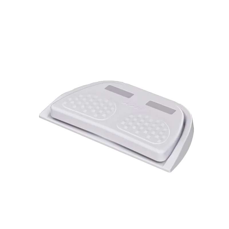 Momentary vs maintained foot switch
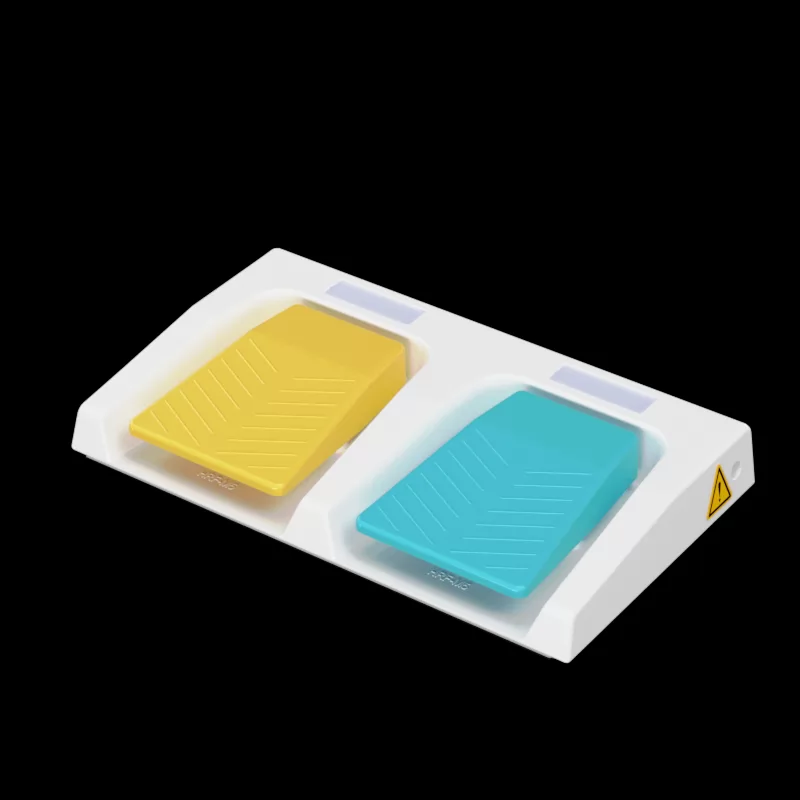 Ergonomic benefits of dual pedal design
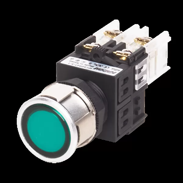 IP67 vs IP68 foot switch for marine use
 Best dual foot switch for hydraulic presses
 Wiring diagram for dual safety foot switches
 Troubleshooting 3-position switch contacts