August. 25, 2026
To troubleshoot a CS-7 limit switch, first identify the exact controller alarm and machine state. Then isolate power, inspect the switch and actuator, perform a continuity test, verify terminals and controller input feedback, and check mechanical alignment, sequence timing, and related safety devices before replacing any component.
I treat a CS-7 limit switch as a mechanically operated position-sensing device. A machine component, cam, lever, roller, or plunger physically moves the actuator, causing internal contacts to change state. The resulting electrical signal tells a relay, PLC input, safety circuit, or machine controller that a defined position has been reached.
A limit-switch fault does not automatically mean that the switch itself has failed. The controller may display an open-limit, not-in-position, or travel-limit error because of a broken conductor, loose terminal, incorrect contact selection, failed input channel, misaligned actuator, or an operation that occurred outside the expected time window. I therefore separate the diagnosis into five possible fault groups: switch failure, wiring failure, controller-input failure, mechanical misalignment, and timing or software failure.
The CS-7 designation may be used differently across equipment documentation, and some maintenance records may refer to an 802T-CS7 or a related catalog number. I never order a replacement from the short label alone. I first record the complete nameplate, actuator style, contact arrangement, enclosure, connector type, voltage, current rating, and machine part number.
Limit switches are used because they provide a direct physical relationship between machine movement and electrical feedback. Unlike a proximity sensor, a mechanical switch requires contact with an actuator or target, but it can provide a clear normally open or normally closed signal without requiring a sensing distance adjustment. That physical action is also the reason mechanical wear, mounting movement, contamination, and excessive force must be considered during troubleshooting.
!
Before beginning CS-7 limit switch troubleshooting, I gather the machine electrical drawings, the controller alarm description, the switch nameplate, the latest maintenance record, and the manufacturer’s wiring information. I also identify whether the switch is part of a normal control circuit or a safety-related circuit. A safety circuit must not be defeated with a jumper simply to make the machine run.
My basic test equipment includes a properly rated multimeter, insulated test leads, a flashlight, terminal screwdrivers, a continuity buzzer if available, a camera or inspection device, and approved lockout/tagout equipment. For controller diagnosis, I also need access to the PLC input display, diagnostic software, relay indicators, or the machine HMI. I use a meter category and voltage range suitable for the installation rather than relying on a generic handheld instrument.
The following information should be written down before wires are removed:
This documentation prevents a common maintenance error: changing several variables at once. If I adjust the actuator, replace the switch, move wires, and reset the PLC in one visit, I may restore operation without identifying the cause. A repeatable record is more useful than a temporary restart because it allows the same fault to be isolated during the next production cycle.
I begin by recording exactly what the controller reports. “Limit switch fault,” “axis not home,” “guard open,” and “sequence timeout” can point to different sections of the circuit even when the operator describes them with the same words. I note whether the fault occurs during startup, forward travel, reverse travel, homing, clamping, guarding, or the return stroke.
Next, I compare the alarm with the physical machine position. If the actuator is visibly pressed but the controller indicates an unoperated state, the problem may be electrical or contact-related. If the actuator never reaches the switch, the switch may be working correctly while the mechanical target, linkage, stop, or timing sequence is incorrect.
I also check whether the error appeared after maintenance, tooling replacement, collision, washdown, electrical cabinet work, or a software change. A fault that begins immediately after a mechanical adjustment should not be treated as an unexplained switch failure. I preserve the alarm history before clearing it because the sequence and timestamp may reveal whether the input changed too early, too late, or not at all.
I apply the machine’s documented electrical safety procedure before opening the switch housing, removing conductors, or entering the guarded area. Lockout/tagout may require isolation of electrical, hydraulic, pneumatic, gravitational, thermal, and stored mechanical energy. I verify zero energy using the approved method for that equipment.
A control-circuit indicator turning off is not enough to prove that the circuit is safe. I check for the presence of voltage at the relevant terminals with a properly rated meter, following the site’s test-before-touch procedure. If more than one supply or backfeed is possible, I identify each source from the electrical drawings.
I stop testing immediately if the enclosure contains unexpected voltage, damaged insulation, burned conductors, moisture, evidence of arcing, or a safety circuit that I cannot positively identify. I also stop if machine movement could occur from gravity, stored pressure, or a remote command. Those conditions require a qualified electrician, controls technician, or service engineer.
With power isolated, I inspect the CS-7 limit switch body, cover, mounting screws, actuator, roller, plunger, lever, cable entry, connector, and surrounding machine structure. I look for cracks, deformation, oil ingress, metal chips, corrosion, loose hardware, crushed cable, and evidence that the actuator has been struck beyond its intended travel. A switch can pass a bench test but fail in service if the actuator is mechanically overloaded.
I then move the machine target or linkage only when the equipment is safely secured and the procedure permits manual movement. The target should contact the actuator in the intended direction and release it cleanly. Side loading, impact loading, excessive overtravel, and contact near the actuator tip can cause inconsistent operation even when the switch appears functional.
I mark the original mounting position before making any adjustment. If the switch has slotted mounting holes, I measure its position from a fixed reference point and photograph the assembly. This gives me a restoration point and helps distinguish a gradual alignment shift from a sudden electrical defect.
I adjust the switch so that the target operates it within the specified operating travel, not at the extreme end of the actuator’s movement. The exact operating angle, force, overtravel, and reset travel must come from the applicable switch documentation. I do not bend a lever or force a plunger to compensate for a target that is incorrectly positioned.
For an adjustable roller lever, I set the roller to meet the target squarely and avoid a sliding impact that can rotate or deform the lever. For a plunger model, I align the target with the plunger axis and provide enough release distance for the contacts to reset. For a rotary actuator, I confirm the correct direction and verify that the mechanism does not exceed its mechanical stop.
After adjustment, I tighten mounting hardware to the equipment’s specified torque and manually cycle the mechanism several times. I record the point at which the actuator operates and the point at which it releases. If the operating position changes from cycle to cycle, I investigate looseness, vibration, wear, or a damaged return spring before proceeding to controller testing.
A CS-7 limit switch continuity test should be performed with the switch isolated from the machine circuit. I remove enough conductors to prevent the PLC input, relay coil, suppression device, or parallel circuit from affecting the meter reading. I label every wire before removal and confirm the terminal numbers against the drawing.
I set the meter to resistance or continuity mode and first touch the test leads together. The meter should show the resistance of the leads, which may be a small value rather than exactly zero. If the leads measure 0.4 ohms, for example, I interpret a switch reading near 0.4 to 1.5 ohms differently from an open reading displayed as OL, but I use the equipment documentation and the meter’s accuracy as the final reference.
I test the suspected contact pair in both actuator states:
| Test condition | Expected result for an NO contact | Expected result for an NC contact |
|---|---|---|
| Actuator released | Open or OL | Closed, low resistance |
| Actuator operated | Closed, low resistance | Open or OL |
| Actuator held near transition | Stable change | Stable change |
The important result is not merely one resistance number. I need to see a clean and repeatable state change as the actuator moves. A contact that remains open, remains closed, changes only when the housing is tapped, or produces rapidly changing resistance may indicate contact damage, contamination, mechanical wear, or an internal spring problem.
I repeat the test at least 10 times for an intermittent complaint and gently flex the cable near the gland, connector, and terminal while watching the meter. I do not flex exposed energized wiring. If the switch changes state reliably but the signal disappears when the cable moves, the probable fault is in the cable, connector, crimp, or terminal rather than the switch body.
A healthy isolated contact normally reads either open circuit or a low resistance value, depending on whether I am testing the NO or NC pair and whether the actuator is released or operated. The exact low-resistance value depends on the switch design, meter leads, contact condition, and test current. A reading that is several ohms higher than the lead resistance, unstable, or inconsistent across repeated cycles deserves further investigation.
I never use continuity alone to approve a safety circuit. A continuity test confirms a contact path under the meter’s limited test conditions; it does not prove that the complete safety function meets the required performance level. Safety relays, dual channels, diagnostics, forced-guided contacts, and controller logic must be checked according to the machine risk assessment and electrical design.
After testing the switch independently, I inspect the wiring from the switch terminals to the nearest terminal block, connector, relay, input module, or safety controller. I check for loose screws, pulled conductors, broken ferrules, damaged insulation, incorrect wire numbers, corrosion, contamination, and conductors inserted into the wrong terminal. I compare the actual installation with the limit switch wiring diagram rather than assuming that wire colors are consistent.
I verify the contact configuration at both ends. A common mistake is wiring an NO contact when the controller expects an NC signal, or using the correct contact pair at the switch but landing the return conductor on the wrong terminal. I also check whether the input is sourcing or sinking, whether a common reference is present, and whether an input fuse or interface relay has opened.
Connectors require special attention because a terminal may appear seated while its crimp has backed out of the housing. I inspect for pushed-back pins, bent contacts, moisture, oxidation, and cable strain. If the machine vibrates, I perform a continuity test from the switch terminal to the controller terminal while moving the cable harness through its normal range.
I measure voltage only when the circuit is energized, the procedure allows it, and I understand the circuit. For a documented 24 VDC input, I may expect a voltage close to the control supply across the designated input path, but I do not apply a universal pass/fail threshold to every CS-7 installation. I compare the reading with the electrical drawing, power-supply tolerance, input-module specification, and the voltage measured at a known-good channel.
A switch can pass continuity testing while the controller still shows the wrong state. I therefore monitor the PLC input, safety relay indicator, remote I/O status, or HMI diagnostic screen while the actuator is operated through its normal position. The input should change at the documented point and return when the actuator releases.
If the contact changes at the switch but the controller input does not, I test progressively along the circuit. I check the switch output, intermediate terminal, connector, relay contact, input common, and controller terminal. This divide-and-test method identifies the point where the signal disappears instead of replacing components based on the alarm label.
A false controller indication may also come from a failed input channel, missing common, incorrect input type, blown fuse, damaged I/O module, network communication issue, or logic condition that masks the real signal. I compare the suspected channel with a documented healthy channel only when the circuit design permits it. I do not move wires between channels on a live machine unless an authorized controls procedure specifically allows the test.
The controller logic may also require two inputs to agree, a safety relay to reset, a guard to close, or a sequence timer to complete. If the CS-7 signal is present but the machine remains faulted, I inspect related safety devices, interposing relays, emergency-stop circuits, guard switches, pressure switches, and permissive conditions. The displayed fault may identify the final failed condition rather than the first cause.
| Symptom | Test result | Probable cause | Next action |
|---|---|---|---|
| Switch remains open | Contact does not close when operated | Failed contacts, wrong terminal pair, or insufficient actuator travel | Confirm COM/NO terminals, then inspect or replace |
| Switch remains closed | NC contact does not open | Welded contacts, actuator not releasing, or incorrect wiring | Check release movement and contact state |
| Controller shows fault, switch tests correctly | No input-state change at PLC | Broken wire, missing common, failed relay, or input-module fault | Test signal path section by section |
| Fault appears during vibration | Resistance changes when cable moves | Loose terminal, damaged conductor, poor connector crimp | Repair termination and secure cable |
| Fault occurs after tooling change | Target misses or strikes actuator | Mechanical misalignment or altered stop position | Recheck target geometry and operating travel |
| Fault occurs only after several seconds | Switch changes correctly but alarm times out | Sequence or timing error | Review PLC timer, motion speed, and permissives |
| Fault occurs randomly | Switch and wiring pass static tests | Vibration, thermal expansion, intermittent contact, or software race condition | Perform repeated cycle testing and trend input state |
For an intermittent fault, I avoid bypassing the switch because a temporary jumper can conceal a dangerous condition and remove the controller’s ability to detect movement. I first define the conditions that reproduce the problem: temperature, machine speed, vibration, direction of travel, production load, washdown, and cycle count. I record the input state and alarm timestamp during each occurrence.
I then perform a controlled wiggle and vibration inspection with power isolated where possible. I check the cable gland, terminal block, connector, actuator mounting, switch cover, and nearby harness supports. A fault that appears after 50 cycles but not during a two-cycle bench test may require extended cycling, thermal observation, or data logging.
For repeatable maintenance work, I use a simple fault-isolation record:
As a practical acceptance check, I may run 20 or more controlled machine cycles after repair when the risk assessment and production procedure allow it. The number should be increased for safety-critical or high-cycle equipment according to the plant’s maintenance standard. I document whether the switch changed state on every cycle, whether the controller recognized every change, and whether any related permissive remained active.
Mechanical alignment is not only a physical issue; it directly affects the signal timing seen by the controller. If a target reaches the CS-7 switch late, the controller may declare a timeout even though the contact changes correctly. If the target reaches the switch too early, the controller may detect an unsafe sequence or an impossible position.
I compare the expected machine sequence with the actual sequence. For example, a clamp-close limit should not operate before the clamp has reached its defined position, and a home limit should not be active during a motion stage that expects it to be released. I review motion speed, cylinder cushioning, belt slip, backlash, worn stops, and changes in tooling geometry.
When the switch, wiring, and input status all test correctly, I examine the PLC or controller logic. I look for altered timer presets, changed input addresses, inverted logic, disabled rungs, stale fault latches, communication delays, and a reset condition that is not being satisfied. A controls engineer should approve software changes, especially when the limit switch participates in a safety or motion-control function.
I also check for related devices that can create the same visible error. A safety door switch, emergency-stop relay, light curtain, pressure switch, overload relay, or motor drive permissive may prevent the sequence from completing. The correct repair may therefore involve a different device even though the operator reports a CS-7 limit fault.
I recommend replacement when the isolated contact fails to change state, the resistance is unstable after terminals and wiring have been confirmed, the actuator or housing is physically damaged, the switch has exceeded its documented mechanical or electrical duty, or repeated adjustment cannot maintain the required operating position. Replacement is also appropriate when the installed switch is no longer available and an approved equivalent has been selected.
Before ordering a CS-7 limit switch replacement, I verify these items:
I do not assume that a similarly shaped switch is electrically interchangeable. A replacement with the wrong contact rating, actuator travel, terminal arrangement, or safety function can create a new failure or an unsafe machine condition. If the original part is marked 802T-CS7, I confirm the exact manufacturer catalog number and application documentation before selecting an alternative.
For purchasing, I compare total cost rather than unit price alone. An illustrative maintenance calculation shows why: if one hour of downtime costs $250, a $40 switch that causes an additional four-hour delay creates a $1,000 production impact before labor and freight are included. Keeping two or three approved spare switches in stock may cost more upfront, but it can reduce emergency freight, extended downtime, and repeat troubleshooting when the component is used on a critical machine.
When I evaluate a Limit Switch Supplier, I review more than the product photograph. I request the full datasheet, contact configuration, operating limits, inspection records, material information, lead time, replacement policy, and confirmation that the supplied part matches the intended application. For quality compliance, I look for documented incoming-material checks, in-process inspection, final inspection, and applicable management-system certifications.
kacon identifies itself as an industrial control manufacturer with limit switches, safety limit switches, compact models, and customized options. Its published company information states that it operates production bases in Incheon, Korea; Yueqing, Zhejiang; and Weihai, Shandong, and that its quality process includes checks on incoming materials, production details, packing, and final inspection. Those statements are useful for supplier screening, but I still request model-specific test records and written compatibility confirmation before approving a substitute.
Delivery risk should be evaluated using measurable information. I ask for standard production lead time, available stock, minimum order quantity, shipping method, export packaging, batch traceability, and the percentage of orders that can be supplied on the required date if the supplier tracks that metric. For critical equipment, I also ask whether the supplier can provide a first-article sample, dimensional drawing, and technical response within the maintenance window.
kacon also presents OEM and ODM support covering housing design, actuator configuration, contact configuration, cable or connector options, and electrical specifications. That can be relevant when a discontinued CS-7 assembly cannot be replaced without modifying the mounting or wiring. I would still require a controlled engineering review, sample validation, insulation and continuity checks, mechanical cycle testing, and approval from the equipment owner before changing the installed design.
Use the following decision path after applying the site’s safety procedure:
Is the machine alarm specific and repeatable?
Does the actuator reach and release the switch correctly?
Does the NO or NC contact change state consistently?
Does the signal arrive at the controller input?
Does the controller recognize the correct state at the correct time?
Is the fault safety-related or still unresolved?
I stop field troubleshooting when the machine cannot be secured against unexpected movement, when the circuit contains unidentified energy, when a safety device would need to be bypassed, or when the fault involves an unfamiliar controller or safety PLC. I also stop when the switch is part of a certified safety function and the available drawings do not identify the required architecture. Continuing under those conditions creates more risk than information.
A qualified technician or service engineer should be called when the input module, safety relay, PLC program, networked I/O, or motion controller may be involved. Escalation is also necessary when repeated replacement does not resolve the alarm, when the machine has experienced a collision, or when the switch operates outside the manufacturer’s mechanical or electrical limits. The escalation package should include photographs, wiring references, meter readings, alarm codes, cycle counts, and all adjustments already made.
How do I troubleshoot issues with a CS-7 limit switch? I use a controlled sequence: identify the exact error, isolate all energy, inspect the actuator and target, test the correct contacts with a multimeter, verify wiring and controller feedback, and then investigate alignment, timing, software, and related safety devices. This method separates a defective switch from a wiring fault, false controller indication, mechanical problem, or sequence error.
I do not bypass the switch to force production, and I do not select a replacement from appearance alone. I confirm the complete catalog number, NO/NC configuration, actuator style, electrical rating, mounting details, environmental requirements, and supplier documentation. When safety boundaries, controller logic, or stored energy are unclear, I stop and involve a qualified professional. Proper CS-7 limit switch troubleshooting ends with documented test results, controlled machine cycles, and a corrective action that can be repeated by the next technician.
 Momentary vs maintained foot switch
 Ergonomic benefits of dual pedal design
 IP67 vs IP68 foot switch for marine use
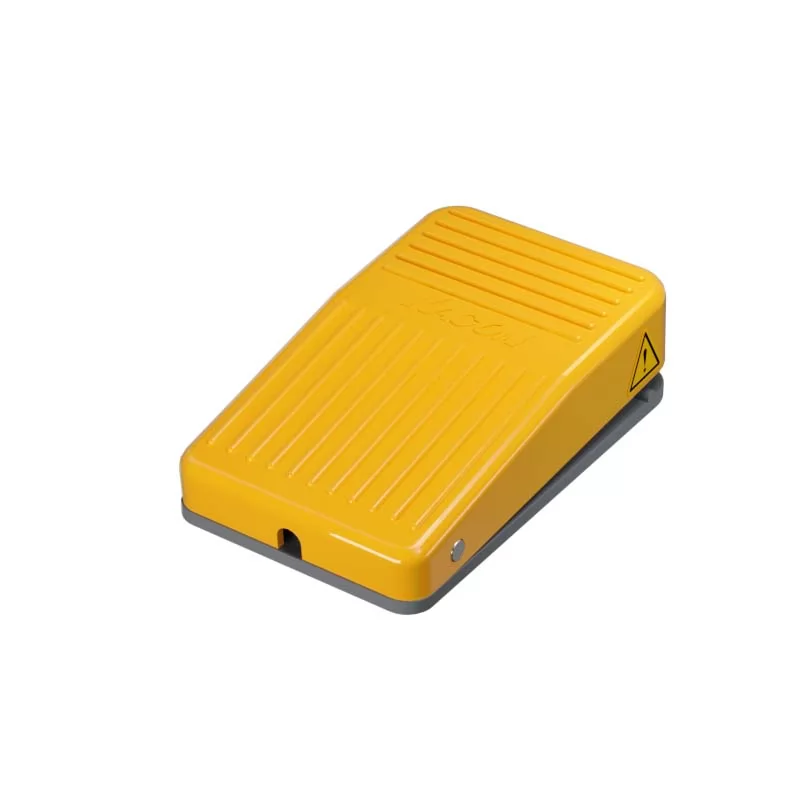 Best dual foot switch for hydraulic presses
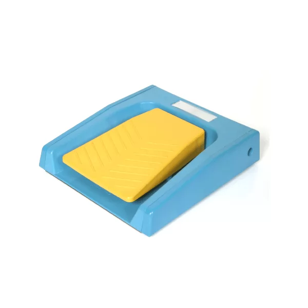 Wiring diagram for dual safety foot switches
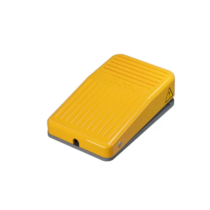 Troubleshooting 3-position switch contacts