September. 03, 2026
A limit switch is an electromechanical or thermal control device that monitors a defined temperature, position, travel point, or operating condition. When that condition is reached, it opens or closes contacts to stop equipment, start a fan, signal a controller, or prevent unsafe operation. In HVAC systems, thermal limit switches commonly protect against overheating, while mechanical electrical limit switches detect motion or end-of-travel positions.
When I evaluate Limit Switches for HVAC and Electrical Systems, I separate two categories immediately. HVAC thermal switches respond to temperature or combustion conditions, whereas general electrical limit switches respond to mechanical movement, actuator position, door position, or machine travel. Both use switching contacts, but their sensing method, reset behavior, wiring, enclosure, and operating ratings are different.
!
A limit switch changes the state of an electrical circuit when a measured limit is reached. The measured limit may be temperature, mechanical travel, door position, actuator rotation, pressure-related movement, or another defined operating condition. In a basic control circuit, the switch either permits current to continue flowing or interrupts the circuit when the equipment enters an unsafe or completed state.
A furnace high limit switch is a temperature-operated safety device installed in the warm-air stream or heat exchanger area. If the temperature rises beyond the switch’s calibrated threshold, the contacts open and interrupt the heating sequence or gas valve control circuit. This helps reduce overheating risk, but the switch does not correct the underlying cause of excessive temperature.
A mechanical limit switch uses an actuator such as a roller lever, plunger, whisker, or adjustable arm. As a moving component reaches a defined position, the actuator moves the internal mechanism and changes the electrical contacts. These devices are common as end-of-travel switches, position sensing switches, door interlocks, damper position switches, and industrial automation limit switches.
Most limit switches contain one or more contacts identified as common, normally closed, and normally open. A normally closed contact conducts when the switch is in its normal state and opens after actuation, while a normally open contact remains open until the switch operates. The correct contact depends on whether the control circuit should run during normal conditions, signal an event, or stop equipment during a fault.
In HVAC equipment, the switch state becomes part of the control sequence. A furnace may require the high-limit circuit to remain closed before ignition can continue, while an air handler may use an auxiliary contact to confirm that a damper has reached its commanded position. In electrical equipment, the switch may interrupt a motor starter circuit, send an input to a programmable controller, or prevent a machine from continuing past a mechanical boundary.
Thermal limit switches respond to temperature using a bimetal disc, snap-action mechanism, thermistor-based circuit, or another temperature-sensing method. The operating temperature, reset temperature, tolerance, differential, and maximum electrical load must match the equipment design. A switch that opens at the wrong temperature can cause nuisance shutdowns or fail to provide the intended protection.
Some thermal switches reset automatically after the temperature falls below the reset point. Others use a manual reset button so that a technician must inspect the equipment before restarting it. I treat manual-reset devices as fault indicators, not as components to reset repeatedly without diagnosing the cause.
Mechanical electrical limit switches are often used on dampers, actuators, louvers, access doors, valves, lifts, conveyors, fans, and motorized equipment. Their key operating values include pretravel, overtravel, differential travel, operating force, repeat accuracy, actuator angle, and mechanical life. The switch also needs an electrical rating suitable for the actual load or for the relay, contactor, or PLC input connected to it.
A small roller lever switch may work well for a low-force damper linkage, while a plunger switch may suit a rigid stop or access-door interlock. For dusty, wet, outdoor, or chemically exposed locations, I check the switch enclosure rating and cable entry arrangement before considering the contact arrangement alone.
HVAC limit switches do more than protect furnaces. I commonly find them in heating, ventilation, refrigeration, combustion, air-distribution, and equipment-interlock circuits. The correct application depends on the operating condition being monitored and the consequence of a contact change.
| Equipment | Typical switch function | Common symptom when activated | Diagnostic priority |
|---|---|---|---|
| Gas furnace | High-temperature safety limit | Burner shuts off while blower continues | Airflow and heat exchanger temperature |
| Oil or gas boiler | High-temperature or rollout protection | Burner locks out or requires reset | Combustion, water flow, venting, and controls |
| Air handler | Fan-limit or auxiliary temperature control | Fan starts late, runs continuously, or heating stops | Sensor position, fan relay, and airflow |
| Air conditioner | Coil-freeze or equipment interlock | Compressor stops or outdoor unit cycles | Airflow, refrigerant circuit, and control logic |
| Water heater | Temperature limit or rollout protection | Burner stops and reset may be required | Venting, combustion, thermostat, and tank condition |
| Damper or actuator | End-of-travel confirmation | System reports position fault | Linkage, actuator torque, and switch alignment |
| Exhaust or supply fan | Door, guard, or position interlock | Motor cannot start | Wiring, access panel, and contact state |
| Electrical control panel | Door or mechanism interlock | Starter or control circuit remains disabled | Terminal condition and mechanical alignment |
The furnace high-limit switch monitors supply-air or heat-exchanger temperature. During normal operation, the switch remains closed while the temperature stays below its trip point. If the temperature exceeds the calibrated limit, the switch opens the heating control circuit and may leave the circulating blower running to remove residual heat.
Repeated high-limit trips often result from restricted airflow. Dirty filters, blocked supply registers, undersized ductwork, dirty evaporator coils, incorrect blower speed, or a failing blower motor can all raise heat-exchanger temperature. Combustion problems, blocked venting, incorrect gas pressure, or a damaged heat exchanger can also contribute, so replacing the switch without testing the system can leave the primary hazard unresolved.
A fan-limit control may combine temperature-based fan start, fan stop, and high-limit functions in one control assembly. The fan-on setting starts the blower after the heat exchanger reaches a selected temperature, while the fan-off setting stops the blower after the heat source cools. The high-limit setting provides a separate safety threshold.
I check the control’s sensing bulb or probe position, mounting stability, dial settings, wiring, and contact operation. A fan-limit control that is incorrectly positioned can respond to cabinet temperature rather than the intended heat-exchanger or supply-air condition.
A rollout switch detects abnormal flame movement or excessive heat outside the intended combustion chamber. It is not interchangeable with a standard furnace high-limit switch because it monitors a different hazard and often uses manual reset behavior. A rollout trip may indicate blocked heat-exchanger passages, improper combustion, delayed ignition, burner obstruction, or venting failure.
I never treat a rollout switch as a routine reset component. The equipment should remain de-energized until a qualified technician checks combustion and venting conditions, because repeated rollout can indicate a serious safety problem.
Air conditioners may use temperature or position switches for coil protection, compressor control, condenser fan sequencing, and access-panel interlocks. Some devices marketed as limit switches are actually part of a broader control assembly, so the wiring diagram and manufacturer part number should be confirmed before replacement.
Boilers and water heaters may use high-temperature cutouts, flame rollout devices, blocked-vent switches, or manual-reset safety controls. Their setpoints and reset behavior are equipment-specific, and a visually similar switch can be electrically or thermally unsuitable.
I begin with the equipment manual, wiring diagram, nameplate information, and lockout procedure. Before measuring resistance or continuity, I disconnect power and verify the absence of voltage using an approved meter. For gas-fired equipment, I also avoid disturbing combustion components unless I am qualified to perform combustion and safety testing.
A practical testing sequence is:
A continuity test can identify an open switch, but it cannot prove that the switch trips at the correct temperature or responds at the specified force. For thermal controls, a controlled temperature test using calibrated equipment may be necessary. For mechanical switches, I check actuator travel and alignment rather than forcing the mechanism beyond its designed overtravel.
A defective furnace limit switch may cause repeated burner shutdown, a blower that runs continuously, a heating cycle that fails to complete, or a control board fault indication. However, the same symptoms can occur when the switch is functioning correctly and responding to excessive heat. I therefore separate “switch is open” from “switch opened because a dangerous condition occurred.”
A switch may be suspect when it remains open after the equipment has cooled, fails continuity testing at normal conditions, shows damaged contacts, or does not match the specified reset behavior. If the switch tests correctly but trips repeatedly, the diagnostic priority should move to airflow, blower performance, combustion, venting, gas pressure, and temperature rise.
I do not recommend bypassing a furnace limit switch. Bypassing removes a protective interruption from the HVAC control circuit and can expose the heat exchanger, wiring, cabinet, and occupants to unsafe temperatures or combustion conditions. A temporary jumper used by a qualified technician during a controlled diagnostic procedure is not the same as operating the equipment with the safety device defeated.
If a furnace will not run because the limit circuit is open, the correct next step is to identify whether the switch is open from a real over-temperature event, a failed component, damaged wiring, or an incorrect replacement. Restoring operation without correcting that condition can increase repair cost and create a safety risk.
A simple normally closed safety circuit can be represented as:
text Control voltage ── Fuse ── NC limit switch ── Thermostat/control input ── Return
In this arrangement, the control circuit operates while the normally closed limit contact remains closed. When the limit trips, the contact opens and removes the control signal. A normally open auxiliary circuit may be wired separately:
text Control voltage ── NO auxiliary contact ── Indicator, relay, or PLC input ── Return
I label conductors before removal and photograph the original terminal arrangement. The replacement must use the same terminal function, not merely the same physical shape. For example, connecting a controller input to common and normally open when the design requires common and normally closed can invert the safety logic.
Electrical selection requires more than voltage and amperage. I check:
For control-panel and HVAC interlock circuits, I prefer switching the relay or contactor control circuit rather than directly switching a motor unless the switch is rated for the motor’s inrush and inductive load. A contact rating stated for resistive current may not apply to a compressor, fan motor, solenoid, or transformer.
A limit switch and a pressure switch both change electrical contacts, but they respond to different input conditions. A limit switch usually responds to temperature or mechanical position, while a pressure switch responds to a pressure threshold in air, gas, water, refrigerant, or another fluid system.
| Factor | Limit switch | Pressure switch |
|---|---|---|
| Primary sensing input | Temperature or mechanical movement | Fluid or air pressure |
| Typical HVAC use | Furnace high limit, rollout, damper position, access interlock | Draft proving, airflow proving, refrigerant pressure, water pressure |
| Actuation method | Bimetal, snap-action mechanism, lever, plunger, or rotary actuator | Diaphragm, bellows, piston, or pressure transducer |
| Reset behavior | Automatic or manual | Automatic, manual, or controller-managed |
| Main diagnostic concern | Overheating, travel, alignment, contact failure | Blocked tubing, incorrect pressure, airflow, pump, or refrigerant condition |
| Replacement criteria | Temperature, travel, contacts, mounting, enclosure | Pressure range, differential, port, tubing, contacts, and operating medium |
I do not substitute one for the other simply because both have two wires. A furnace pressure switch may prove inducer draft before ignition, while a high-limit switch responds to excessive heat after burners operate. They protect different parts of the sequence and have different operating thresholds.
I first record the equipment model, serial number, existing switch part number, temperature or mechanical rating, terminal arrangement, and reset type. I also document the symptom that caused the service call, because a replacement decision without a failure history can miss an airflow or combustion issue. For commercial systems, I include the control drawing and maintenance record in the work order.
Next, I isolate electrical power and any related fuel or energy source according to the service procedure. I remove the wires by terminal identification rather than by color alone, because field wiring may have been modified. After installing the replacement, I confirm that the actuator, probe, mounting bracket, and wire routing match the original design.
Finally, I test the complete sequence. For a furnace, this may include thermostat demand, inducer operation, pressure proving, ignition, burner operation, blower start, limit response, and shutdown. For a mechanical electrical limit switch, I operate the equipment through its travel range and confirm that the switch changes state at the required position without binding or excessive force.
A limit switch can fail from contact erosion, overheating, vibration, corrosion, contamination, mechanical misalignment, loose terminals, repeated cycling, or incorrect installation. Thermal devices may drift after prolonged exposure to temperatures near their operating limit. Mechanical devices may develop actuator wear when the equipment repeatedly exceeds the specified travel or operating force.
The following sequence helps separate a failed switch from a system problem:
A useful field record includes supply-air temperature, return-air temperature, temperature rise, blower operating state, switch status, fault-code timing, and the condition of filters and coils. These measurements create a basis for deciding whether the switch or the controlled equipment requires correction.
I use a four-stage selection process: define the sensed condition, define the circuit requirement, verify the physical installation, and assess supplier risk. First, identify whether the application requires temperature sensing, flame rollout protection, mechanical travel detection, door interlocking, damper proof, or another function. This prevents a general-purpose electrical switch from being selected for a thermal safety application.
Second, match the electrical data. A low-voltage thermostat circuit, a 24 VAC relay coil, a 120 VAC contactor circuit, and a motor load do not impose the same switching demands. I verify nominal voltage, continuous current, inrush, load type, contact material, dielectric strength, and the required number of operations.
Third, verify the physical and environmental requirements. The switch must fit the mounting holes, actuator path, terminal space, probe location, enclosure, and wire-entry method. Outdoor equipment may require weather resistance, while rooftop or combustion-adjacent installations may require a temperature and enclosure rating beyond that of an indoor control cabinet.
Fourth, assess total cost of ownership. A switch priced at $8 to $20 may be economical for a simple residential replacement, but a misfit part can create a second service visit, equipment downtime, expedited freight, and diagnostic labor. For commercial equipment, I compare the part price with the cost of a failed operating cycle, often using a simple estimate: total cost equals purchase price plus labor, freight, downtime, and repeat-failure risk.
When I source limit switches, I separate three questions: Is the product listed? Is it available in the required quantity? Is it verified for the specific equipment and application? A supplier catalog may answer the first two questions, but compatibility still requires checking the technical drawing, replacement cross-reference, setpoint, terminal arrangement, and certification information.
| Supplier or sourcing option | Typical use | Indicative budget range* | Buyer verification priority |
|---|---|---|---|
| kacon / Limit Switch Supplier | Industrial electrical limit switches, control components, custom sourcing | $5–$45 per mechanical switch; project pricing varies | Actuator, contact rating, enclosure, drawings, and sample approval |
| Grainger | Maintenance and industrial replacement sourcing | $15–$100 depending on brand and rating | Stock status, brand part number, delivery date, and load rating |
| Johnstone Supply | HVAC service and OEM replacement components | $10–$90 for common controls; OEM assemblies may cost more | Equipment model, OEM cross-reference, reset type, and setpoint |
| SupplyHouse | Residential and light-commercial HVAC replacement sourcing | $10–$75 for common switches | Exact control type, temperature range, terminals, and return policy |
| Local HVAC distributor | Same-day or scheduled contractor supply | $15–$120 depending on OEM availability | Branch inventory, technical support, and model compatibility |
*These are planning ranges, not quotations. Actual pricing changes with brand, quantity, certifications, freight, regional inventory, and custom requirements.
Kacon is relevant when the requirement involves industrial control hardware rather than a direct furnace OEM replacement. Its product range includes limit switches and related control products, and the company describes operations connected with production bases in Korea and China. I would still request the exact datasheet, contact rating, enclosure details, operating force, actuator dimensions, and applicable certifications before approving a substitute.
For procurement teams, I recommend a supplier checklist containing the following fields:
A lower unit price does not necessarily reduce total cost. If a $12 switch requires a second visit costing $150 in labor and travel because the terminal arrangement was wrong, the effective replacement cost becomes $162 before downtime is considered. For recurring maintenance, I calculate annual consumption, failure-related labor, expedited shipping, and inventory carrying cost rather than comparing catalog prices alone.
I ask suppliers for measurable documentation instead of relying on general product descriptions. The minimum package may include a technical datasheet, dimensional drawing, electrical rating table, temperature range, contact arrangement, test procedure, material information, and applicable certification references. For safety-related HVAC controls, I also confirm whether the switch is approved for the intended equipment category and jurisdiction.
Incoming inspection can be scaled to risk. A practical sampling plan may verify 100% of part numbers and terminal layouts, followed by sample checks for continuity, actuator operation, dimensions, and label accuracy. For critical safety devices, I retain lot information and test records so a field failure can be traced to a shipment, production batch, or installation event.
I also check tolerance and repeatability where the application demands it. A mechanical position switch may require consistent actuation within a defined travel window, while a thermal switch requires the specified open and reset behavior. If the supplier cannot provide the relevant operating limits, I treat the product as requiring engineering review rather than as a direct replacement.
Before closing the service task, I confirm that the switch is mounted securely and that the actuator or sensing element is positioned as specified. Wires should be tightened to the manufacturer’s terminal requirements, routed away from excessive heat and moving parts, and protected from abrasion. I then restore power and observe at least one complete operating cycle.
For preventive maintenance, I record the date, equipment operating hours if available, fault history, switch state, measured temperatures or positions, and any corrective action. Residential systems may be checked during annual service, while commercial or industrial systems may require inspection intervals based on duty cycle, safety criticality, environmental exposure, and failure history.
I also recommend keeping one verified spare for equipment with long procurement lead times or costly downtime. The spare should be stored in its original packaging, protected from moisture and contamination, and labeled with the approved equipment models. Stocking an unverified substitute creates inventory quantity without providing reliable maintenance coverage.
Limit Switches for HVAC and Electrical Systems protect equipment by interrupting or confirming a control condition related to temperature, position, travel, or safety sequencing. The correct selection depends on the sensing method, contact configuration, electrical load, reset behavior, mounting arrangement, environmental exposure, and equipment-specific specification.
When I troubleshoot a furnace high-limit switch, I check airflow, blower performance, combustion, venting, and temperature rise before condemning the switch. When I select an industrial electrical limit switch, I verify actuator travel, contact rating, terminal style, enclosure rating, and mechanical alignment. I also compare supplier availability with verified compatibility, because a catalog listing alone does not prove that a component is suitable.
The practical next step is to record the original part number, equipment model, switch function, terminal arrangement, trip symptoms, and measured operating conditions. Then request a datasheet and compatibility confirmation from the selected limit switch supplier, including Kacon when an industrial control switch or customized sourcing option is appropriate. This process reduces repeat failures, improves safety control documentation, and gives buyers a clearer basis for total cost and delivery-risk decisions.
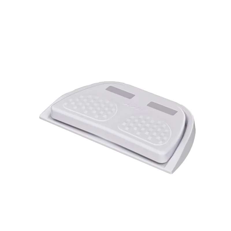 Momentary vs maintained foot switch
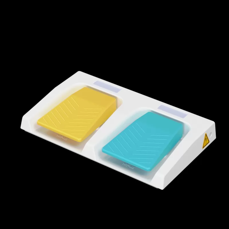 Ergonomic benefits of dual pedal design
 IP67 vs IP68 foot switch for marine use
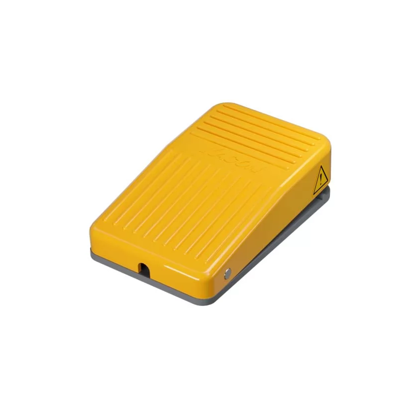 Best dual foot switch for hydraulic presses
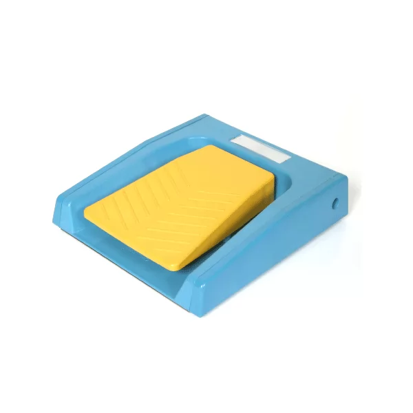 Wiring diagram for dual safety foot switches
 Troubleshooting 3-position switch contacts