September. 02, 2026
A limit switch is a mechanically actuated electromechanical sensor that detects position or travel and changes normally open or normally closed contacts. The resulting electrical signal can be sent to a PLC, relay, counter, or machine safety circuit to indicate that equipment has reached a defined position, end-of-travel point, or operating condition.
When I evaluate limit switches in automation systems, I treat them as both sensing devices and control inputs. Unlike a sensor that detects an object without physical contact, a mechanical limit switch responds when a moving machine component physically presses, rolls across, deflects, or pulls an actuator. That movement changes the internal contact state and allows the control system to start, stop, sequence, count, or protect a machine.
The practical value depends on correct actuator selection, mounting alignment, contact configuration, environmental protection, electrical rating, and maintenance planning. A switch may cost relatively little compared with a motor or PLC, but an incorrectly installed device can create false stops, missed position signals, mechanical damage, or unsafe machine behavior.
!
A limit switch is an electromechanical position sensor with three basic elements: an actuator, an internal switching mechanism, and electrical terminals. The actuator moves when it contacts a machine part, and that movement operates contacts inside the switch housing. The contacts then open or close a control circuit according to the selected wiring arrangement.
In a typical automated machine, the limit switch does not measure position continuously. Instead, it confirms that a component has crossed a defined mechanical point. For example, a conveyor may use one switch to confirm that a pallet has arrived, while a linear actuator may use two switches to identify its forward and reverse travel limits.
The term “limit” refers to a boundary or control point, but the device can perform more than end-of-travel detection. I commonly see limit switches used for position sensing, counting, sequencing, machine interlocks, presence confirmation, and protection against over-travel.
| Component | Function | Engineering concern |
|---|---|---|
| Actuator | Receives movement from the machine | Must tolerate the direction, speed, force, and travel pattern |
| Switching mechanism | Converts actuator movement into contact movement | Snap action, contact bounce, and repeatability affect signal quality |
| Housing | Protects internal parts | Enclosure rating must match dust, water, oil, and impact exposure |
| Terminals | Connect the switch to control wiring | Terminal style and contact arrangement must match the PLC circuit |
| Mounting body | Secures the device to the machine | Alignment prevents side loading and premature wear |
I explain how limit switches work through a six-stage operating sequence: target movement, actuator contact, internal travel, contact change, PLC input processing, and machine response. This complete sequence is more useful than describing the switch only as an on/off device because every stage can introduce a failure.
A snap-action design changes contacts rapidly after the actuator reaches its operating point. This helps reduce the period in which the contacts are transitioning, although contact bounce can still occur and must be handled through PLC filtering, timer logic, or suitable relay circuitry.
A normally open contact, commonly identified as NO, remains open when the actuator is in its released state. When the actuator is pressed, the contact closes and allows current to flow through the connected circuit. This arrangement is useful when the control system only needs a positive signal after a machine reaches a position.
A normally closed contact, or NC, remains closed when the actuator is released and opens when the actuator is pressed. NC wiring is often preferred for fault monitoring because a broken wire, disconnected terminal, or loss of control power can appear as an abnormal open condition. However, NC logic alone does not make a standard limit switch a certified safety device.
For ordinary automation, I select NO or NC according to the PLC input logic and the desired default state. For safety-related functions, I also check the complete architecture, diagnostic coverage, fault exclusion, stopping performance, and applicable requirements such as ISO 13849-1 or IEC 62061.
The actuator determines how the switch interacts with the machine. I do not select an actuator only from a catalog drawing; I compare the motion direction, available travel, impact force, approach angle, machine speed, and expected number of operating cycles.
A plunger actuator moves along the axis of the switch body when a machine surface presses it. Push plunger designs are suitable for direct end-of-travel confirmation where the moving part approaches in a reasonably controlled line.
Roller plunger versions use a rolling element to reduce sliding friction. Cross-roller plungers can handle certain lateral approaches more effectively than plain plungers, but the machine target must still be positioned to avoid excessive side loading.
A roller lever uses a pivoting arm with a roller at its end. The roller allows a moving surface to pass across the actuator while converting linear movement into rotational movement inside the switch.
I use roller levers for conveyors, slides, indexing mechanisms, and machine doors where the target may approach from the side. Adjustable roller levers provide additional setup flexibility, but the adjustment must be locked after commissioning so vibration cannot change the switching point.
A plain lever actuator provides a wider contact surface than a plunger and can be suitable for moderate-speed mechanical movement. A whisker actuator uses a thin flexible wire or spring element to detect objects passing from several directions.
Whisker designs are useful for lightweight parts, narrow targets, and applications where a rigid actuator could obstruct the product flow. They are not appropriate when the moving object can apply excessive force, catch the wire, or produce repeated high-energy impacts.
Rotary limit switches detect rotation rather than direct linear contact. They may be used on camshafts, hoists, winches, valve mechanisms, and multi-position machinery.
The engineering decision depends on the required number of switching positions, shaft speed, torque, and mechanical indexing method. Rotary designs are particularly useful when a machine’s position is best represented by angular movement rather than a single linear endpoint.
Rod actuators use a straight or spring-loaded rod to detect movement over a longer or less precise approach path. kacon’s listed limit switch range includes spring rod, spring wire, plastic-tip, and metal-tip configurations, which shows how actuator material and flexibility can be matched to the target motion.
Pull-action switches operate when a cable or rod is pulled rather than pushed. I consider these designs for emergency-stop systems, conveyor pull-cord arrangements, and applications where the sensing point must extend over a distance. A pull-action product must be evaluated separately from an ordinary position switch because cable tension, reset behavior, and safety certification may be different.
Correct installation begins with the switch travel specifications. Pre-travel is the actuator movement from its free position to the point where the contacts change state. The operating point is the specific position at which the electrical transition occurs, while over-travel is the additional allowable movement after switching.
Reset travel describes how far the actuator must return before the contacts change back to their original state. If the machine reverses only slightly and does not provide enough reset travel, the PLC may continue to see the switch as active. I therefore verify both actuation and release distances during commissioning.
A mechanical limit switch should not be used as the machine’s physical crash stop unless the product documentation specifically permits that function. I install a separate mechanical stop or motion-control limit so the machine structure absorbs stopping energy instead of the switch actuator.
Alignment is equally important. The target should contact a roller or lever in the intended direction, remain within the specified travel range, and avoid impact near the actuator’s extreme position. Misalignment can bend a lever, crack a mounting bracket, create intermittent signals, or increase wear at the actuator pivot.
Contact bounce is another practical concern. When mechanical contacts close, they may open and close several times within a short interval before stabilizing. A PLC program can filter the input with a timer, commonly in the range of several milliseconds, but the exact value must be tested against machine speed so filtering does not delay a required stop.
Before wiring a limit switch, I confirm the contact diagram, rated voltage, current, terminal markings, PLC input type, and whether the circuit is standard control or safety-related. Typical terminal markings include COM, NO, and NC, although manufacturers may use different numbering systems.
Turn off and isolate the relevant power sources before opening the control cabinet or machine junction box. Verify the absence of voltage with a properly rated meter, and follow the site’s lockout and tagout procedure.
For a simple arrival signal, connect the PLC input through COM and NO so the input turns on only when the actuator is pressed. For fault-monitoring logic, connect through COM and NC so the input is present in the released state and disappears when the switch actuates or the wiring is interrupted.
A common 24 VDC arrangement routes the positive supply through the switch contact and into the PLC input, with the PLC common connected to the control supply return. Some PLC input modules use sourcing logic and others use sinking logic, so I follow the PLC manufacturer’s wiring diagram rather than assuming all inputs use the same polarity.
Use the correct cable gland, strain relief, conductor size, and enclosure entry method. Keep low-voltage sensor wiring separated from high-current motor cables where possible to reduce electrical interference and prevent cable damage.
With power restored, operate the actuator manually and confirm that the voltage changes at the PLC input terminal. Then verify that the PLC diagnostic state, HMI indication, alarm logic, and machine response match the electrical design.
A limit switch failure rarely has only one cause. I use the following checklist before replacing the device because the actual problem may be mechanical, electrical, environmental, or software-related.
To test a switch with a multimeter, I first isolate the circuit and identify COM, NO, and NC. I measure continuity between COM and NC with the actuator released, then operate the switch and confirm that COM-NC opens while COM-NO closes. If the electrical state changes inconsistently during repeated manual operation, I inspect for mechanical wear, contamination, or internal contact damage.
The difference between a limit switch and a proximity sensor is the detection method. A limit switch requires physical contact with a moving target, while a proximity sensor detects an object without direct mechanical contact through inductive, capacitive, magnetic, ultrasonic, or photoelectric principles.
| Factor | Mechanical limit switch | Proximity sensor |
|---|---|---|
| Detection method | Physical actuator movement | Non-contact field, light, sound, or capacitance |
| Contact output | Often NO, NC, or changeover | Usually electronic PNP, NPN, or two-wire output |
| Mechanical wear | Present at actuator and contact mechanism | Lower mechanical wear because there is no actuator |
| Target requirements | Must physically reach the actuator | Must meet sensing-distance and material requirements |
| Contamination tolerance | Depends on enclosure and actuator design | Depends on sensing technology and environment |
| Wiring complexity | Often simple dry-contact wiring | Requires correct supply voltage and output compatibility |
| Typical strength | Direct, visible, low-cost position confirmation | Fast, repeatable non-contact detection |
| Typical limitation | Wear, impact, and alignment sensitivity | False detection, target material limits, and electronic failure |
I choose a limit switch when direct mechanical confirmation is acceptable, the target path is predictable, and a dry contact simplifies integration. I consider a proximity sensor when actuator wear, noise, contamination, or high cycling speed makes physical contact undesirable.
Neither technology is automatically safer. A proximity sensor can fail electronically or lose detection because of target distance, while a mechanical switch can fail through broken wiring or welded contacts. For a safety function, I select a device and control architecture that are specifically rated for the required safety category or performance level.
Limit switch applications in industrial automation include position detection, end-of-travel control, counting, sequencing, interlocks, and machine protection. I normally define the required machine action first and then select the switch type that provides the correct signal at the correct physical point.
A limit switch can confirm that a cylinder, slide, lift table, or actuator has reached a defined position. The PLC may then permit the next step only after receiving the expected input.
Two switches can identify the forward and reverse limits of a linear mechanism. The control program can stop the motor, remove a drive command, or generate an alarm if the expected switch does not activate within a specified time.
A conveyor belt limit switch can detect pallet arrival, product accumulation, chute position, belt drift, or access-door status. Roller levers and spring rods are common choices because they tolerate passing objects better than fixed plungers.
A robotic arm end-of-travel switch can provide an additional confirmation for a service position, gripper mechanism, fixture clamp, or auxiliary axis. It should not replace the robot controller’s certified motion limits unless the design specifically integrates the switch into an approved safety system.
Each actuation can create a discrete event for a counter or sequence step. Contact bounce must be addressed so one physical product does not create multiple counts.
A switch can confirm that a guard is closed, a fixture is clamped, or a removable component is in place. Standard position switches may support process interlocks, but guard-related protective functions generally require safety-rated switches, monitored contacts, suitable safety relays, and validated control logic.
A standard limit switch should not automatically be treated as a safety device. Safety-rated applications require more than an NC contact; they may require positive-opening contacts, dual-channel wiring, fault detection, redundancy, safety relays, and validation according to the machine risk assessment.
For a guard interlock, I check whether the switch is designed for guard monitoring and whether the actuator can be defeated easily. A safety relay can monitor two channels, detect certain short circuits, and control the safety output devices, but the complete circuit still requires correct installation and validation.
Fail-safe NC logic is useful because an open circuit can be detected as a fault instead of being interpreted as a safe machine-ready condition. However, NC wiring cannot detect every failure, including some contact welding or mechanical bypass conditions. The selected device, mounting arrangement, diagnostic coverage, and stopping performance must be considered together.
I use the following decision framework when selecting a limit switch for automated machinery.
| Application condition | Recommended direction |
|---|---|
| Direct axial movement | Plunger or roller plunger |
| Side approach on a conveyor | Roller lever or spring rod |
| Lightweight object from multiple directions | Whisker or flexible rod |
| Rotating mechanism | Rotary actuator |
| Long-distance pull or cable monitoring | Pull-action design |
| Dust or water exposure | Enclosure rating suitable for the site, such as IP67 where specified |
| PLC input with simple dry contact | NO, NC, or changeover contact based on logic |
| Guard or protective function | Safety-rated switch and safety control system |
| High cycle count | Verify mechanical and electrical operating-life ratings |
| High inductive load | Use a relay, contactor interface, or suppression device |
| Tight installation space | Compact vertical or snap-action body |
I also compare the electrical load, switching frequency, operating temperature, vibration, shock, cable routing, and replacement availability. A switch rated for millions of mechanical operations may still have a lower electrical life when switching a motor coil directly, so load suppression and interface relays can affect total service life.
When I review a Limit Switch Supplier, I examine the product range, available actuators, documentation, compliance claims, manufacturing footprint, and support process rather than relying on product naming alone. Kacon identifies itself as a manufacturer of industrial safety controls and medical device components, with production bases in Incheon, South Korea; Yueqing, Zhejiang, China; and Weihai, Shandong, China. The company states that it has 70 years of experience and supplies industrial control products for automation, conveyors, aerial platforms, forklifts, cranes, and other equipment categories.
For limit switch selection, Kacon lists KXM, KXL, and KXN series products with actuator options including push plungers, roller plungers, cross-roller plungers, roller levers, adjustable levers, spring rods, and spring wires. The KXL series page specifies IP67 protection, CE, UL, and RoHS compliance claims, and a rated mechanical life exceeding 10 million operations. Those figures are useful for an initial comparison, but I would still request the exact model datasheet, electrical-life rating, test conditions, and certificate scope before approving a production design.
Delivery risk should be evaluated separately from product specifications. I ask the supplier to confirm the exact model, actuator configuration, contact arrangement, packaging quantity, sample lead time, production lead time, minimum order quantity, replacement policy, and available safety documentation. A supplier with multiple production locations may provide sourcing flexibility, but buyers should obtain written confirmation of which factory will produce the approved part and whether changes require customer notification.
The purchase price is only one part of limit switch cost. I calculate total cost of ownership using the device price, installation labor, wiring, interface components, scheduled inspections, replacement parts, downtime exposure, and inventory carrying cost.
For example, a $20 switch that causes a two-hour line stoppage may cost more than a $35 switch if the machine loses $500 per hour in production contribution. The calculation is simple: a $15 purchase difference is minor compared with a potential $1,000 downtime event. This does not mean the most expensive product is automatically appropriate; it means the comparison should include failure consequences.
A practical maintenance plan records actuator condition, mounting tightness, contact state, cable strain, enclosure condition, and PLC diagnostic history. I recommend checking the switch during scheduled machine inspections and testing safety-related functions according to the site’s documented safety program rather than waiting for a failure.
What are limit switches and how do they work in automation systems? They are mechanically actuated electromechanical devices that convert machine movement into NO, NC, or changeover electrical signals for PLCs, relays, counters, interlocks, and control circuits. The machine target moves the actuator, the actuator reaches its operating point, the internal contacts change state, and the control system responds according to its programmed logic.
I choose a plunger, roller, lever, whisker, rotary, rod, or pull-action design according to motion direction, travel, impact, cycle frequency, and available space. I also verify pre-travel, over-travel, reset travel, alignment, mechanical stops, contact bounce, enclosure rating, electrical load, and maintenance access before installation.
For ordinary position detection, a standard mechanical limit switch can provide a direct and easily tested signal. For protective functions, I use a safety-rated device with suitable NC logic, safety relays, redundancy, diagnostics, and validation. When comparing a limit switch supplier such as kacon, I review model-specific specifications, compliance documentation, production arrangements, lead times, and total cost of ownership before approving the component for automated equipment.
 Momentary vs maintained foot switch
 Ergonomic benefits of dual pedal design
 IP67 vs IP68 foot switch for marine use
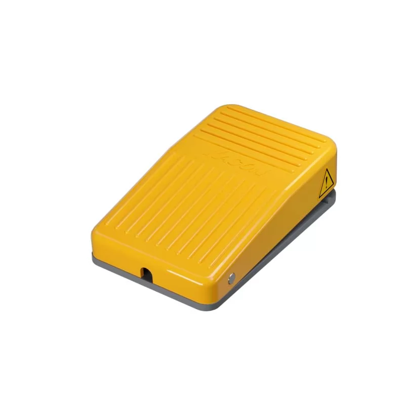 Best dual foot switch for hydraulic presses
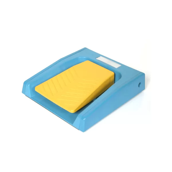 Wiring diagram for dual safety foot switches
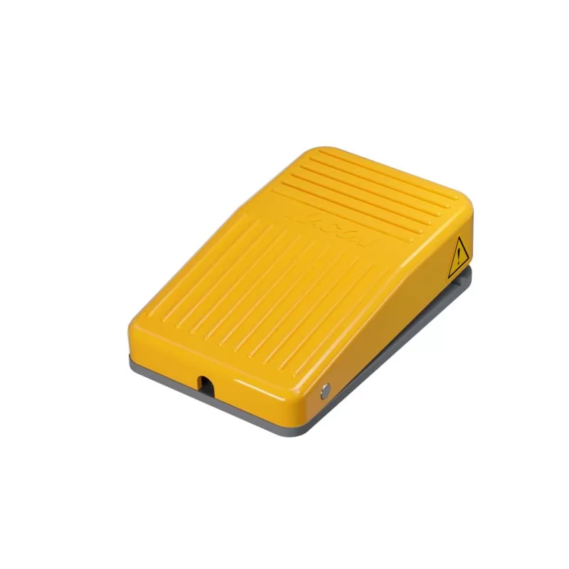 Troubleshooting 3-position switch contacts