September. 01, 2026
Square D limit switch problems usually come from five areas: actuator misalignment, insufficient mechanical travel, damaged or sticking contacts, wiring faults, and incorrect controller-input interpretation. I troubleshoot these devices by isolating power, inspecting the mounting and actuator, checking normally open and normally closed contacts, verifying terminal wiring, and testing the voltage reaching the PLC, furnace control, motor starter, or CNC input. A replacement should be installed only after the mechanical and electrical tests confirm that the switch itself has failed.
When I investigate a Square D limit switch that will not activate, stays closed, produces an intermittent signal, or causes a machine fault, I separate the problem into five diagnostic layers. The first layer is mechanical movement, including the actuator, roller, lever, plunger, mounting bracket, and machine target. The second layer is the internal contact mechanism, followed by wiring, controller input, and application-specific logic. This order prevents a technician from replacing a working switch when the actual problem is a loose bracket, a broken conductor, or an incorrect PLC input configuration.
A Square D limit switch is a mechanically operated electrical switch used to detect position, travel, door movement, overtravel, or the end of a machine sequence. Many Class 9007 models use snap-action contacts and provide a combination of normally open and normally closed circuits. Depending on the model, the switch may operate in one direction, both clockwise and counterclockwise directions, or through a neutral-position arrangement.
For safe work, I begin with the machine’s electrical drawings, the exact catalog number, and the control voltage. I apply the site’s lockout/tagout procedure before removing covers or disconnecting conductors, and I verify the absence of voltage with a properly rated meter. Live voltage testing should be performed only by qualified personnel using the correct category-rated test equipment and insulated probes. A continuity reading taken on an energized circuit can damage the meter and expose the technician to arc-flash or shock hazards.
!
A Square D limit switch converts mechanical movement into an electrical contact change. When a machine cam, door, slide, actuator, or moving assembly contacts the switch, the actuator moves and changes the state of internal contacts. The controller then interprets that change as a position signal, stop command, interlock condition, or sequence confirmation.
In a typical single-pole double-throw arrangement, the common terminal is connected to either the normally closed or normally open contact depending on actuator position. With the actuator released, COM-to-NC should normally show continuity, while COM-to-NO should normally remain open. When the actuator reaches its operating point, the contact state changes, although the exact behavior depends on the catalog number and contact arrangement.
Some Class 9007 devices have rotary heads that can be configured for clockwise or counterclockwise operation. Certain models support operation from either direction, while neutral-position versions use separate contact sets for movement on opposite sides of center. I never assume the contact sequence from the switch appearance; I confirm it from the device label, wiring diagram, and instruction sheet.
A mechanical limit switch differs from a proximity sensor because it requires physical contact with the target. That makes actuator position and machine travel important, but it also gives the technician a direct mechanical indication of whether the switch is being operated. A proximity sensor can avoid physical wear, while a limit switch may be easier to diagnose with a continuity meter and can provide a familiar hardwired interlock.
Actuator misalignment is one of the most frequent causes of a Square D limit switch not activating. The machine target may pass beside a roller, contact the lever at an incorrect angle, or strike the actuator too close to its mechanical limit. In each case, the switch may fail to reach its operating point or may experience excessive side loading.
I inspect the target path with the machine stopped and the actuator released. The target should contact the roller or lever in the intended direction and should not scrape across the housing. I also check whether the actuator returns fully after the target passes; incomplete return can leave the contacts in the wrong state during the next machine cycle.
The correction may involve repositioning the switch, adjusting the target, rotating the head, or selecting a different actuator style. On compatible Class 9007 models, the head can be repositioned to suit the approach direction, but the adjustment must follow the manufacturer’s instructions. I record the original position before making changes so that the final setting can be compared with the machine drawing.
A limit switch may be electrically functional but never receive enough mechanical travel to change state. This occurs when a cam is too short, a door opens only partially, a slide stops before reaching the switch, or a replacement switch has a different operating point. The result often appears as a dead switch even though the internal contacts test correctly.
I manually operate the actuator with power isolated and observe whether the contact changes state before the actuator reaches its stop. I then compare that movement with the actual machine target. If the target moves the actuator only 1 or 2 millimeters but the switch requires more movement, the system needs mechanical correction rather than a new switch.
Overtravel is also dangerous. A service bulletin for Square D control equipment identifies actuator overtravel as a cause of broken limit-switch parts. I therefore make sure the machine target operates the switch and then moves away, instead of forcing the actuator against the housing or internal stop.
A sticking actuator can result from dust, metal chips, coolant residue, oxidation, or a damaged return spring. In a CNC machine, chips may restrict a roller or plunger, while in a furnace or outdoor installation, heat, moisture, and corrosion may affect the mechanism. An actuator that does not return consistently can create intermittent PLC alarms or repeated machine stops.
I first check free movement without applying excessive force. The actuator should move through its intended range and return without hesitation, grinding, or remaining partially depressed. I do not spray general-purpose lubricant into an enclosed switch unless the product instructions specifically permit it, because contamination can migrate to the contacts or affect insulation.
If cleaning does not restore free movement, I treat the actuator or internal mechanism as suspect. A switch that works during a slow manual test but fails during normal machine speed may have marginal return force, contact bounce, or mechanical drag. Replacing the complete switch assembly is usually safer than trying to rebuild a sealed mechanism in the field.
Bent levers and worn rollers change the point at which the switch operates. A roller may develop a flat spot, a lever may twist after an impact, or the switch body may shift because of loose mounting screws. Even a small change in position can cause a door interlock or machine stop circuit to operate inconsistently.
I check the switch body, mounting holes, fasteners, actuator shaft, lever, roller, conduit entry, and terminal cover. I mark the switch body and mounting plate with a paint witness line where appropriate; if the lines move apart after several cycles, the mounting is not stable. The fastener torque should follow the equipment drawing or switch instruction sheet rather than an arbitrary field value.
The machine target must also be inspected. A worn cam or loose guard can produce the same symptoms as a defective switch. I correct the mechanical source before installing a replacement, otherwise the new component may experience the same impact and fail again.
Some Square D limit switch models are direction-sensitive. A lever may be configured for clockwise operation, counterclockwise operation, or a specific reset direction. Installing the same-looking head in the wrong configuration can make the switch appear inactive even when the contacts and wiring are correct.
I verify the actuator direction against the machine’s travel. For a bidirectional application, I confirm that the selected model actually supports both directions; a one-direction model cannot always be converted into a true two-direction device. Neutral-position versions must be tested separately because one contact set may change during clockwise movement and another during counterclockwise movement.
Internal contact failure includes welded contacts, burned contacts, high contact resistance, broken contact springs, and failure of the snap mechanism. A switch may show continuity on a low-current meter but fail when carrying a relay coil or contactor circuit. Conversely, a contact may remain electrically open even though the actuator moves normally.
I test the contact in both released and actuated positions. If the meter shows unstable resistance, a delayed transition, or measurable resistance where a closed contact should be near zero ohms, I isolate the switch from the circuit and repeat the test directly at the terminals. I do not rely on a single beep from a continuity tester as proof of reliable operation.
Contact ratings also matter. One Square D 9007C data sheet lists a 600-volt, 10-amp configuration, but allowable make, break, and continuous-carrying values vary by voltage, load type, contact material, and model. A replacement must be selected from its own rating table, especially when switching motor contactor coils, solenoids, heaters, or DC loads.
When reviewing a Square D limit switch wiring diagram, I identify the common, normally closed, and normally open terminals before touching the conductors. The terminal markings may be abbreviated, and a field wire may not match the expected color convention. The machine schematic, not wire color alone, determines how the contact is intended to function.
A standard diagnostic sequence is:
The expected pattern for a conventional SPDT switch is continuity between COM and NC when released, no continuity between COM and NO when released, and the opposite condition when actuated. The exact resistance target depends on the meter and test leads, but a closed contact should generally read close to the lead-resistance baseline rather than several ohms or an unstable value. A technician should compare the result with the manufacturer’s specifications when the circuit carries a sensitive input or low-level signal.
Loose terminals are common in vibration-heavy equipment. I inspect for stripped screws, damaged conductors, crushed insulation, corrosion, loose ferrules, and wires pulled tight against the conduit entry. I also check whether the terminal block has been overheated by a load above the switch rating.
To test a Square D limit switch with a multimeter, I use two separate methods: an unpowered continuity test and an energized voltage test. The continuity test determines whether the contacts change state mechanically. The voltage test determines whether the correct control voltage reaches the switch and continues through the circuit to the controller or relay.
I set the meter to resistance or continuity and verify that the test leads work by touching them together. With the switch isolated from the circuit, I measure COM-to-NC and COM-to-NO in the released position. I then operate the actuator through its normal travel and watch for a clean, repeatable transition.
A useful record includes the released reading, actuated reading, actuator direction, and whether the switch returns immediately. For example, a normal SPDT pattern may be recorded as follows:
| Test point | Actuator released | Actuator actuated | Interpretation |
|---|---|---|---|
| COM to NC | Near 0 Ω | Open or OL | Normal NC behavior |
| COM to NO | Open or OL | Near 0 Ω | Normal NO behavior |
| COM to NC during slow movement | Clean transition | Clean transition | Contacts change correctly |
| COM to NO during repeated cycles | Stable transition | Stable transition | Repeatability is acceptable |
If the readings are correct at the switch but incorrect at the PLC terminal, I move to the wiring and input circuit. If the readings fail directly at the switch, I inspect the actuator and then consider replacement. If continuity changes only when the housing or cable is moved, I suspect a terminal, conductor, or internal connection problem.
For voltage testing, I restore the circuit only after reinstalling covers where required and establishing a safe measurement method. I measure the control voltage at the source, at the switch input terminal, at the switch output terminal, and at the receiving input. The expected value depends on the application, such as 24 VDC, 120 VAC, or another control voltage specified on the drawing.
A voltage present at the switch input but absent at the output while the contact should be closed indicates a contact, terminal, or actuator problem. Voltage missing at the switch input points toward a fuse, relay, emergency-stop circuit, upstream interlock, broken conductor, or control-power issue. Voltage present at the output but absent at the PLC input suggests a downstream wiring, common-reference, input-card, or configuration problem.
I avoid shorting probes across terminals and do not use a resistance range on an energized circuit. For 24 VDC PLC systems, I also verify the polarity and common reference because a switched positive signal and a switched negative signal produce different diagnostic results. In safety-related circuits, I follow the applicable site procedure and do not bypass an interlock merely to make the machine run.
I use the following decision tree when a machine reports a limit switch fault:
Does the actuator move correctly?
If no, correct alignment, travel, contamination, bending, or mounting problems.
Does the contact state change at the switch terminals?
If no, inspect the actuator and internal contacts.
Does the changed state reach the terminal block or junction point?
If no, repair the conductor, terminal, connector, or cable.
Does the correct voltage reach the controller input?
If no, inspect the control circuit, fuse, relay, common, and upstream devices.
Does the controller recognize the signal?
If no, check input configuration, logic inversion, diagnostics, and the input module.
Does the application respond correctly?
If no, investigate PLC logic, motor-control sequencing, furnace control interpretation, or CNC parameter logic.
I escalate the problem when a switch fails repeatability testing, shows heat damage, has a cracked enclosure, operates beyond its mechanical limits, or switches a load outside its published rating. I also escalate when a safety circuit cannot be validated after repair. A temporary jumper may be permitted only under an approved maintenance procedure, with the machine secured and the bypass removed before production resumes.
Furnace troubleshooting requires caution because a furnace limit switch may be part of a temperature-protection circuit rather than a simple position sensor. A continuously running blower can be caused by an open high-limit circuit, a stuck relay, a control-board fault, restricted airflow, an overheated heat exchanger, or an incorrectly wired replacement. Resetting or bypassing the switch without finding the temperature cause can create a serious safety hazard.
I first identify whether the device is a furnace temperature limit control or a mechanical position limit switch. They may both be called “limit switches,” but their sensing principles and replacement requirements are different. I then check the furnace manufacturer’s wiring diagram, airflow condition, filter, blower operation, burner sequence, and control-board fault code before testing the switch itself.
If the furnace limit opens repeatedly, I treat the trip as a symptom requiring investigation. A technician should not repeatedly reset the control and return the unit to service without checking airflow, heat input, fan performance, and temperature rise. HVAC-specific service procedures and applicable electrical and combustion-safety rules take priority over a generic continuity test.
In PLC systems, I compare the physical switch state with the PLC input LED and the online input status. If the switch changes state but the PLC does not, I test the input voltage at the card terminals and verify the input common. If the PLC sees the signal but the sequence does not advance, the problem may be ladder logic, a permissive, a timer, a reset condition, or another interlock.
A normally closed limit circuit is often used so that a broken wire can appear as a fault, but the control logic must be designed for that arrangement. If the program expects an active-low input and the replacement is wired as active-high, the machine can report a persistent fault even when the switch operates correctly. I therefore compare the replacement wiring with both the electrical schematic and the PLC logic description.
In a motor-control circuit, the limit switch may be wired in series with a contactor coil, relay, reversing circuit, or starter interlock. I check whether the switch is intended to stop motion in one direction while allowing reverse travel. A limit switch that opens both directional circuits can create a no-start condition unrelated to the switch itself.
I measure control voltage across the switch and across the contactor coil under the relevant operating command. A voltage drop across a closed limit contact indicates contact resistance or a loose terminal. If the switch is rated for a control circuit but is directly switching a motor load, I stop and verify the design because motor inrush and inductive interruption can exceed the contact rating.
CNC limit switches are affected by chips, coolant, vibration, rapid axis movement, and machine reference procedures. I inspect the switch target, cable carrier, connector, and input diagnostics before assuming the switch has failed. An intermittent alarm that appears only during rapid travel may indicate cable flexing or mounting vibration rather than contact failure.
I verify whether the control uses normally open or normally closed logic and whether the machine expects the switch to change during overtravel, homing, or reference return. After correction, I test the axis at reduced speed and confirm that the control receives the expected signal before returning to normal operation. I also document the switch position because a small alignment change can alter repeatability and machine travel protection.
I recommend Square D limit switch replacement when the internal contact fails direct-terminal testing, the actuator mechanism is damaged, the enclosure is cracked, the switch has suffered heat or arc damage, or the device cannot achieve repeatable operation after alignment. Replacement is also appropriate when the existing model is no longer suitable for the load, environmental exposure, travel direction, or safety function. Repairing a sealed industrial switch is usually not an acceptable substitute for installing a correctly rated device.
Before ordering, I record:
A visually similar switch may not be electrically interchangeable. For example, two devices can share the same body size but differ in contact count, neutral-position behavior, or clockwise and counterclockwise operation. I verify the complete part number and compare the wiring before accepting a cross-reference.
For purchasing, a maintenance department may source the original Square D device, an approved equivalent, or a compatible industrial limit switch from another manufacturer. A Limit Switch Supplier such as kacon may be considered when the buyer needs alternative industrial switch families, custom actuator arrangements, or a broader control-component supply channel. kacon identifies limit switches, control switches, safety devices, relays, terminal blocks, and related industrial components among its product categories, and its company information lists production bases in Korea and China.
The total cost of ownership includes more than the unit price. I calculate labor for diagnosis and installation, machine downtime, expedited freight, production scrap, repeat failures, and spare-parts inventory. A $40 switch that causes a four-hour outage may cost more than a $75 replacement that is immediately compatible and supported by a documented cross-reference.
I recommend inspecting exposed limit switches during scheduled maintenance rather than waiting for a machine alarm. The inspection should include actuator freedom, target alignment, mounting security, terminal condition, cable strain, enclosure damage, and evidence of contamination. On equipment with repeated cycles, the maintenance record should include cycle count or operating hours when available.
A practical checklist includes:
I also maintain a spare-parts record that separates complete switches from interchangeable heads, levers, rollers, covers, and contact blocks. This prevents a buyer from ordering a low-cost component that cannot be installed on the existing body. For critical machines, I keep at least one verified spare and document its storage condition, testing date, and approved application.
What are the common issues and troubleshooting tips for Square D limit switches? The main problems are actuator misalignment, insufficient travel, sticking or bent mechanical parts, loose mounting, contact failure, wiring faults, incorrect voltage, and controller-side configuration errors. I troubleshoot them in order: isolate power, inspect the actuator and mounting, test NO and NC continuity, check terminals and wiring, verify control voltage, confirm the controller input, and then replace the switch only when the evidence identifies the switch as the failed component.
For furnace applications, I distinguish temperature-limit controls from mechanical position switches and investigate repeated trips before resetting the system. For PLC, motor-control, and CNC equipment, I compare the physical contact state with the voltage at the input and the logic status in the controller. When selecting a Square D limit switch replacement, I match the complete catalog number, contact arrangement, actuator type, direction, mounting, environmental rating, and electrical load. A documented troubleshooting checklist and approved supplier such as kacon can reduce repeat downtime, incorrect substitutions, and unnecessary inventory costs.
 Momentary vs maintained foot switch
 Ergonomic benefits of dual pedal design
 IP67 vs IP68 foot switch for marine use
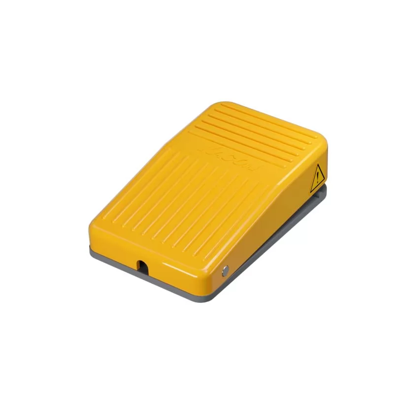 Best dual foot switch for hydraulic presses
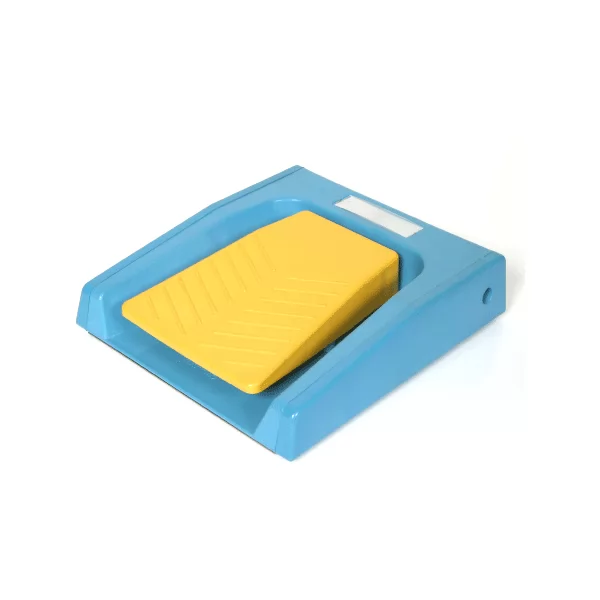 Wiring diagram for dual safety foot switches
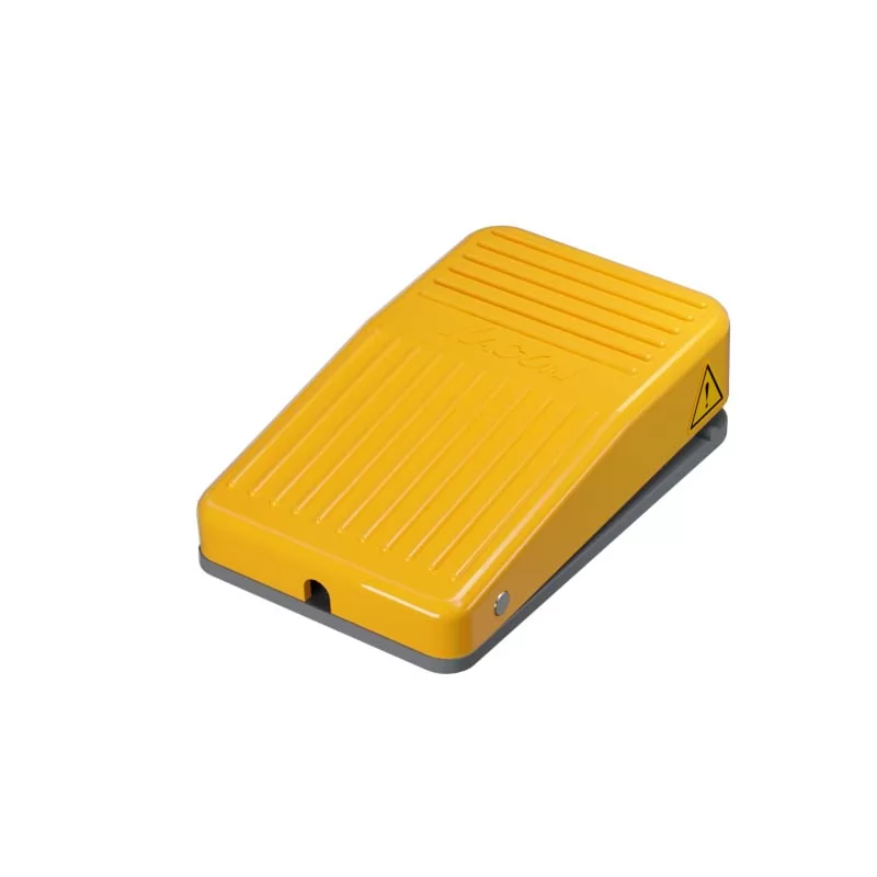 Troubleshooting 3-position switch contacts