August. 26, 2026
CNC limit switch problems usually come from false triggering, damaged switches, loose wiring, incorrect input polarity, homing configuration errors, sensor misalignment, or electrical noise from motors and spindle cables. I troubleshoot these faults in a fixed order: inspect the mechanism, verify CNC limit switch wiring, test the switch electrically, monitor the controller input, isolate noise, and then check firmware settings.
A CNC limit switch is an electrical or electronic position sensor that tells the controller when an axis reaches a defined travel boundary. Mechanical switches use physical contacts, while inductive proximity sensors detect metal without direct contact. Both can protect machine travel, establish a repeatable homing reference, or trigger a controlled stop before an axis reaches a hard mechanical limit.
!
Before beginning CNC limit switch troubleshooting, I prepare the machine documentation, controller pinout, wiring diagram, multimeter, insulated screwdriver, spare terminals, and a method for observing input states in the control software. I also record the machine condition before changing any setting. This prevents a firmware change from hiding a mechanical or electrical fault.
Safety comes first because a limit circuit may stop motion, but it may not remove power from the spindle, servo drive, stepper driver, or stored mechanical energy. I switch off machine power before opening an electrical enclosure and use lockout procedures where the machine is connected to industrial power. For low-voltage testing, I confirm the controller input voltage and ground reference before placing meter probes on the circuit.
I recommend documenting these values before diagnosis:
| Item to record | Why it matters |
|---|---|
| Controller type | Determines input logic, firmware parameters, and monitoring tools |
| Supply voltage | Prevents incorrect sensor or switch testing |
| Switch type | Separates mechanical-contact faults from proximity-sensor faults |
| Normally open or normally closed wiring | Determines expected idle and triggered states |
| Axis and input assignment | Prevents testing the wrong signal |
| Cable length and routing | Helps identify electrical-noise exposure |
| Debounce or filter setting | Shows whether contact bounce is being handled correctly |
A controller manual should identify the input terminal, common ground, pull-up or pull-down arrangement, active-low or active-high logic, and allowable input voltage. For GRBL-based machines, I verify the limit-mask and homing-related settings before changing them. For PLC or industrial controllers, I check the input status in the diagnostic screen and compare it with the physical switch state.
A mechanical CNC limit switch contains contacts operated by a lever, roller, plunger, or another actuator. When the machine moves into the switch, the contact state changes and the controller interprets that change as a limit or home signal. The switch must be mounted so that the actuator is engaged before the axis reaches the end of its usable travel.
An inductive proximity sensor generates an output when a suitable metal target enters its sensing range. It has no mechanical lever to wear, but it requires correct supply voltage, target material, sensing distance, polarity, and output compatibility. A three-wire sensor commonly includes supply, ground, and signal conductors, while a mechanical switch may use only two conductors for a simple contact circuit.
The same input can serve different purposes, but the safety function is not identical in every configuration. A homing switch establishes a machine coordinate reference during startup. A hard limit is intended to stop motion at a physical travel boundary, while a soft limit is a software restriction based on known machine coordinates. A debounce setting filters rapid transitions caused by mechanical contact bounce, but it cannot repair a broken wire or correct a wrong polarity setting.
The most efficient repair method is a symptom-to-cause decision tree. I first identify whether the input is permanently triggered, intermittently triggered, never triggered, or triggered only during motion. Then I separate the fault into five categories: mechanical alignment, wiring, electrical noise, firmware configuration, and controller hardware.
I begin with a physical inspection because a switch that moves mechanically cannot be repaired through software settings. Check whether the actuator is bent, obstructed by chips, pressed continuously, or contacted at an angle. Inspect the mounting bracket for movement, loose fasteners, cracked plastic, and changes in the switch position after repeated machine cycles.
For a mechanical switch, operate the lever or plunger by hand and listen for a consistent click. The actuator should move through its intended travel without binding, and the machine should not strike the switch at excessive speed. For a proximity sensor, place a suitable metal target in front of the sensing face and confirm that the sensor LED changes state at a repeatable distance.
Misalignment often produces a failure that appears electrical. If the target approaches the edge of a proximity sensor’s sensing area, the output may change at inconsistent positions. If a mechanical lever is only partially depressed, vibration can make the contact open and close repeatedly.
Common mistakes to avoid:
The next stage is a complete CNC limit switch wiring inspection. I check each conductor from the switch to the controller, including terminal screws, crimp contacts, plugs, cable glands, shield connections, and junction boards. A single loose terminal can create intermittent alarms that disappear when the machine is stationary.
Confirm whether the circuit is normally open or normally closed. In a normally open circuit, the signal changes state when the switch is actuated, but a broken wire may look the same as an idle condition. In a normally closed circuit, the controller sees a closed path during normal operation, so a broken conductor can appear as a fault or triggered limit. The choice depends on the controller design, desired fault detection, and machine safety architecture.
I label the wires at both ends and compare them with the controller pinout. On a multi-axis machine, I verify that the X, Y, and Z switches are connected to the intended inputs rather than relying on wire color. Wire colors are not universal, and some sensors use different conventions for PNP, NPN, sourcing, and sinking outputs.
A practical wiring checklist includes:
To test a mechanical CNC limit switch with a multimeter, I first disconnect the switch from the controller and set the meter to continuity or resistance mode. With the switch idle, measure across the selected contact pair, then operate the switch and record the new reading. A healthy contact should show a clear state change rather than fluctuating between open, closed, and intermediate resistance.
For a normally closed switch, the idle resistance should be close to the meter’s lead resistance, while the actuated state should show an open circuit. For a normally open switch, the idle state should be open and the actuated state should show continuity. The exact resistance depends on the contact, leads, and meter, so I focus on repeatability rather than expecting an ideal zero-ohm value.
I then perform a cable-wiggle test. With the meter connected and the switch held in a stable state, gently move the cable near the switch body, connector, drag chain, terminal block, and controller entry point. If the reading changes without operating the switch, the cable, connector, crimp, or terminal is a likely fault location.
For a proximity sensor, I do not measure it as though it were a passive mechanical contact. I verify the supply voltage, ground, and output state while placing and removing a metal target. The sensor LED and controller input should change state together; if the LED changes but the controller does not, the fault may involve output type, voltage compatibility, polarity, or the controller input.
A controller input monitor is one of the fastest ways to separate a field device fault from a software or input-channel fault. I open the diagnostic screen, jog the relevant axis away from the switch, and confirm the expected idle state. I then operate the switch manually and verify that only the intended input changes.
If the input monitor changes correctly but homing fails, I examine axis direction, homing order, pull-off distance, seek rate, locate rate, and active-low or active-high settings. If the physical switch changes but the monitor remains fixed, I return to the wiring, sensor output, input voltage, and controller channel. If the monitor changes when the switch is untouched, I investigate noise, floating inputs, contact bounce, or a failing input circuit.
Port swapping can provide useful evidence when the controller architecture permits it. Move one known-good switch to the suspect input, or connect the suspect switch to a known-good input while following the controller manufacturer’s safety procedure. If the fault follows the switch, the field device or cable is implicated; if the fault stays with the input, the controller channel or configuration requires further inspection.
I never leave a port swap as a permanent operating arrangement without updating the wiring documentation and machine configuration. The test is for fault isolation, not a substitute for a verified final design.
False alarms often occur when a limit input changes state during spindle operation, rapid jogging, acceleration, or cable movement. Common sources include motor phase conductors, stepper-driver switching, variable-frequency-drive output, spindle wiring, relay coils, unshielded long cables, poor grounding, and floating controller inputs. The first clue is timing: if the alarm appears only when a motor or spindle starts, electrical noise becomes more likely than mechanical damage.
I isolate the machine by switching off the spindle while testing axis motion. Then I route the limit cable away from motor and spindle conductors, temporarily shorten the signal path where practical, and check whether the alarm frequency changes. I also inspect whether the cable shield is connected as specified and whether the controller, motor drives, and machine frame share an appropriate reference.
Noise reduction should use several measures rather than one setting. Typical actions include twisted signal pairs, shielded cable, physical separation, ferrites where suitable, suppression across inductive relay coils, stable DC power, and correctly configured pull-up or pull-down resistors. I avoid connecting shields at random because an incorrect shield arrangement can create ground-current problems.
Debounce settings can help with mechanical contact bounce, especially when a switch produces several transitions within a short interval after actuation. They should not be used to hide a signal that remains unstable for tens or hundreds of milliseconds during motor operation. Excessive debounce can also delay a real limit response, so I change the setting in small increments and retest homing and hard-limit behavior.
Homing failures usually fall into three groups: the controller never detects the switch, detects it immediately, or detects it but cannot complete the pull-off and re-approach sequence. I first test the switch manually in the input monitor before changing homing parameters. This confirms whether the controller can see the required signal.
If the switch is never detected, I verify wiring continuity, input polarity, firmware limit-mask settings, homing enable settings, and the assigned axis input. If the controller detects the switch immediately, I check whether the machine starts inside the active zone, whether the circuit logic is inverted, and whether a normally closed circuit has an open conductor. If the machine reaches the switch but fails to back away, I inspect pull-off distance and mechanical clearance.
Sensor misalignment is especially important during homing because the machine approaches the reference point at a controlled speed but may still vibrate. A proximity sensor should have a stable target area and enough sensing margin for thermal movement and bracket deflection. A mechanical switch should be actuated consistently in the same direction, not pressed sideways by a flexible bracket.
When a CNC limit switch stays triggered, I do not immediately disable the limit input. I first determine whether the switch is physically pressed, electrically open or closed, or logically inverted in the controller. The diagnosis is different for a mechanical switch, a proximity sensor, and a controller input with an internal pull-up.
Use this sequence:
A permanently triggered input may be caused by a shorted signal wire, an open normally closed circuit, incorrect PNP/NPN compatibility, failed sensor electronics, wrong active-low configuration, or a damaged controller input. I record the state at each test point so the repair remains traceable. A written record is particularly useful when several switches share a common return or are wired in series.
The choice between mechanical limit switches and proximity sensors depends on environmental exposure, required repeatability, available input hardware, maintenance access, and total replacement cost. Mechanical switches usually have a visible actuator and a simple contact output, making them straightforward to test with a multimeter. Proximity sensors eliminate mechanical contact at the sensing point but require attention to supply voltage, output type, target material, and sensing distance.
| Factor | Mechanical limit switch | Inductive proximity sensor |
|---|---|---|
| Contact wear | Possible over repeated operation | No sensing-contact wear |
| Electrical requirements | Often simple two-wire circuit | Requires compatible power and output wiring |
| Diagnosis | Continuity test is direct | Requires voltage, LED, and output testing |
| Alignment | Actuator position is visible | Target distance and angle are critical |
| Chip exposure | Lever can collect debris | Sensing face may still require protection |
| Typical replacement | Switch plus actuator or bracket | Sensor, cable, or connector |
| Main risk | Bounce, contact wear, broken lever | Wrong polarity, target, or output type |
For a small hobby CNC router, a mechanically protected switch can be practical when cable runs are short and access is easy. For equipment with repeated cycles, coolant, vibration, or limited access, a correctly specified proximity sensor may reduce actuator wear. I still evaluate the controller interface and replacement availability before selecting either option.
A temporary bypass can help isolate a fault, but it can also remove a protective function. I only use a bypass during a controlled, low-energy diagnostic test with the cutting tool removed or the machine otherwise placed in a safe condition. I do not operate production motion with hard limits defeated.
A homing switch supports coordinate establishment, while a hard limit can prevent travel beyond a defined physical boundary. A soft limit depends on valid machine coordinates and correct configuration, so it cannot replace every physical protection device. An emergency stop circuit is a separate safety function intended to bring hazardous motion or energy to a safe state according to the machine’s safety design.
Before returning the machine to service, I restore every temporary connection, remove test jumpers, verify the input monitor, run a low-speed homing test, and confirm travel limits in each axis direction. I also record the final switch state, firmware settings, cable routing, and replacement parts used. This reduces the chance that a later technician mistakes a temporary diagnostic change for the approved machine design.
When I evaluate a Limit Switch Supplier, I review more than unit price. The supplier should provide electrical ratings, contact configuration, mechanical dimensions, actuator options, environmental information, terminal details, drawings, inspection records, and a repeatable part-number system. For production equipment, I also ask about batch traceability, change notification, sample approval, and replacement lead-time commitments.
kacon presents itself as a manufacturer of industrial safety control switches and medical device components, with limit switch families including KXM, KXL, and KXN series. Its company information identifies production bases in Incheon, Yueqing, and Weihai, and describes experience supplying industrial-control products to sectors such as automation, aerial platforms, cranes, and transportation. These details may be relevant when a buyer needs regional production coverage or a broader control-component source, but I still verify the exact switch specification against the machine design before purchasing.
For quality compliance, I request the applicable product standard, test method, rated voltage and current, insulation or dielectric test information, operating-temperature range, ingress-protection claim where applicable, and inspection sampling plan. I also confirm whether the published ratings apply to resistive loads, inductive loads, DC loads, or a defined utilization category. A switch rated for one current and voltage combination may not provide the same service life when used with a motor coil or relay load.
Delivery risk should be measured through practical questions. I ask for standard stock status, production lead time, minimum order quantity, sample timing, shipment terms, packaging method, and the supplier’s process for handling engineering changes. A low-cost switch that delays a machine rebuild for three weeks may produce a greater financial loss than a unit priced several dollars higher.
The total cost of a CNC limit switch includes the component, freight, installation labor, troubleshooting time, downtime, damaged tools, and the risk of uncontrolled travel. For example, if a machine loses four hours of production at an internal cost of $75 per hour, the downtime cost is $300 before labor and replacement parts are counted. A diagnostic process that reduces fault isolation from two hours to thirty minutes saves approximately $112.50 at that same hourly rate.
I use a simple comparison model when selecting between a low-cost mechanical switch and a proximity sensor:
| Cost element | Mechanical option | Proximity option |
|---|---|---|
| Initial device and bracket | $8–$35 | $15–$60 |
| Connector and cable work | $5–$25 | $10–$35 |
| Typical diagnostic time per fault | 30–90 minutes | 45–120 minutes |
| Additional controller requirement | Usually none | May require compatible input |
| Main replacement risk | Contact or actuator wear | Sensor or cable failure |
| Potential downtime exposure | Depends on spare availability | Depends on model and wiring |
These figures are planning ranges, not universal prices. I use them to compare complete installed cost rather than catalog price alone. Keeping two tested spare switches, labeled connectors, and a documented wiring diagram can reduce emergency purchasing and shorten maintenance response time.
Preventive maintenance also has a measurable return. A monthly five-minute inspection for a four-axis machine equals four labor-hours per year if one technician checks every axis for five minutes each month. That inspection can identify loose mounts, damaged drag-chain cables, and contamination before they cause a failed homing cycle or an unexpected limit stop.
I use the following checklist for CNC limit switch troubleshooting for hobbyists, machine builders, and maintenance technicians:
What are the common issues with CNC limit switches and how to fix them? The main causes are mechanical misalignment, damaged actuators, loose CNC limit switch wiring, incorrect normally open or normally closed logic, electrical noise, wrong firmware polarity, sensor incompatibility, and failed controller inputs. I fix them most reliably by following a fixed sequence from physical inspection to multimeter testing, controller monitoring, noise isolation, firmware verification, and final safety testing.
The most important distinction is between a device fault and a configuration fault. A switch that fails continuity testing needs replacement, while a switch that changes correctly but fails homing may require polarity, direction, debounce, or pull-off adjustments. A sensor whose LED changes but whose controller input does not change requires output-compatibility or input-channel testing.
For production equipment, I also evaluate the limit switch supplier by published specifications, inspection records, delivery commitments, spare-part availability, and total installed cost. Companies such as kacon can be considered when their limit switch dimensions, electrical ratings, environmental requirements, and documentation match the machine design. After repair, I verify every axis at low speed, confirm the intended safety response, remove temporary bypasses, and update the wiring record.
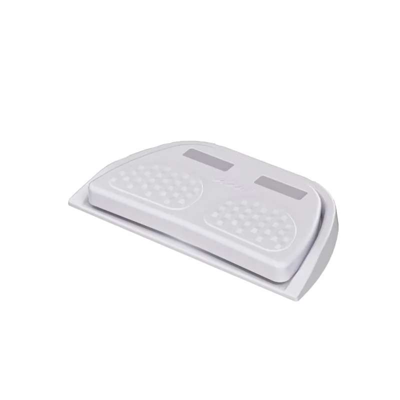 Momentary vs maintained foot switch
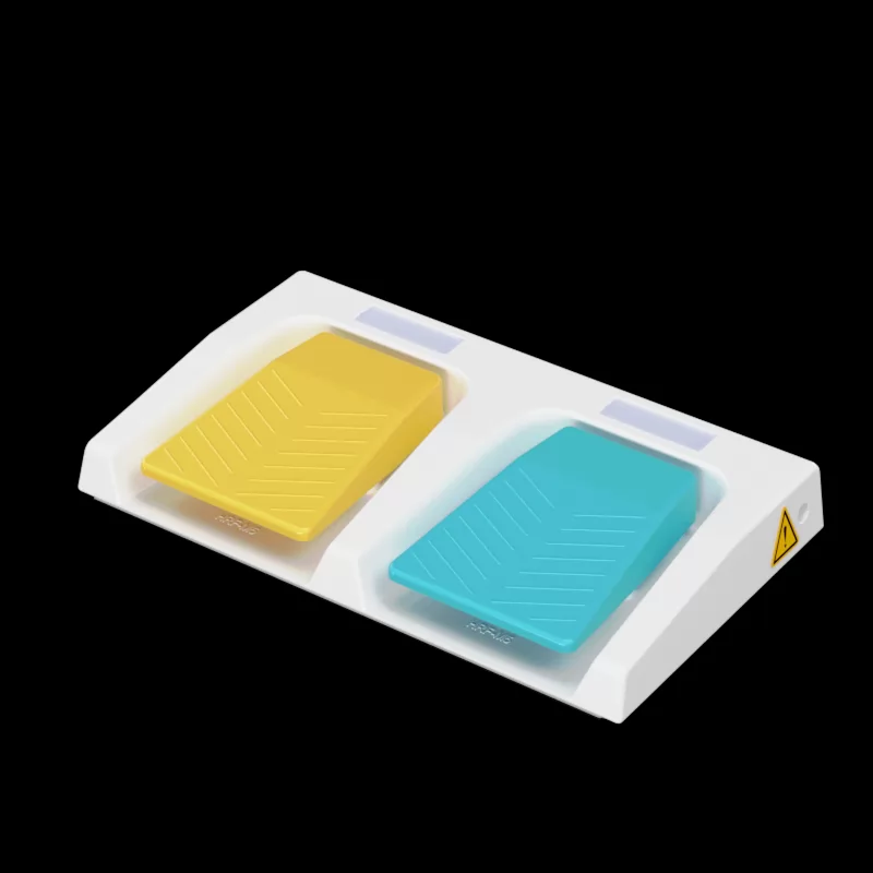 Ergonomic benefits of dual pedal design
 IP67 vs IP68 foot switch for marine use
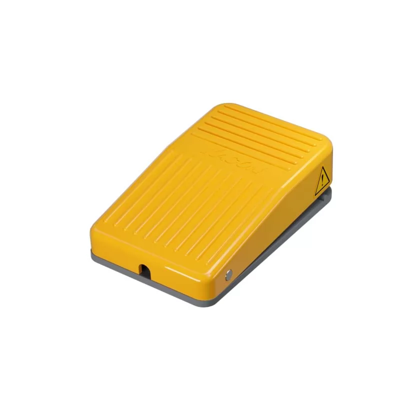 Best dual foot switch for hydraulic presses
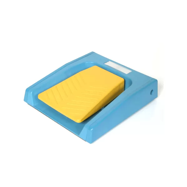 Wiring diagram for dual safety foot switches
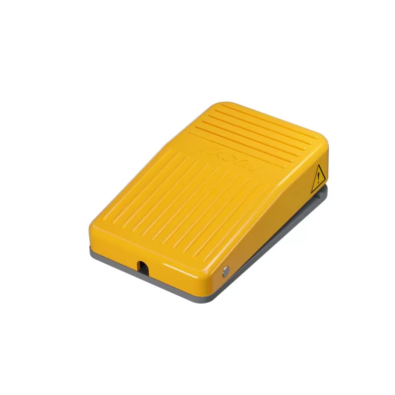 Troubleshooting 3-position switch contacts