• Home
  • Customization
    • Medical Foot Switch
    • Industrial Foot Switch
    • Plastic Footswitch
  • Products
    • Medical Foot Switch
      • Medical Foot Switch
      • Plastic Foot Switch
    • Heavy Duty Footswitch
    • Limit Switch
      • KXM Series Limit Switch
      • KXL Series Limit Switch
      • KXN series Limit Switch
    • Control Switch
      • Small Size Switch
      • Ø16 Switch
      • 22·30 Control Switch
      • Metal Switch
      • Safety Emergency Switch
      • BOX Switch
      • Rotary Switch Disconnector
      • Accessory
      • Power Push Button
      • Pilot Lamp
    • Safety Door Switch
    • Safety Relay Module
    • Safety Light Curtain
    • Relay
      • Safety Relays & Sockets
      • SSR
      • General Purpose Relay
      • KMY Economic Relay
      • Slim Relay
      • Heavy Duty Relay
      • Relay Socket
    • Terminal Block
    • Buzzer
    • Timer
    • Temperature Controller
    • Micro Switch
    • Circuit Protection
    • Tower Light
    • Power Supply
  • About KACON
  • Solution
    • Solution Proposal
    • Successful Cases
  • Technical Support
    • Download
    • Project Management
    • FAQ
  • Media
    • News
    • Exhibition
    • Video
  • Contact
Zhejiang Kacon Electric Co., Ltd.
  • Home
  • Customization
    • Medical Foot Switch
    • Industrial Foot Switch
    • Plastic Footswitch
  • Products
    • Medical Foot Switch
      • Medical Foot Switch
      • Plastic Foot Switch
    • Heavy Duty Footswitch
    • Limit Switch
      • KXM Series Limit Switch
      • KXL Series Limit Switch
      • KXN series Limit Switch
    • Control Switch
      • Small Size Switch
      • Ø16 Switch
      • 22·30 Control Switch
      • Metal Switch
      • Safety Emergency Switch
      • BOX Switch
      • Rotary Switch Disconnector
      • Accessory
      • Power Push Button
      • Pilot Lamp
    • Safety Door Switch
    • Safety Relay Module
    • Safety Light Curtain
    • Relay
      • Safety Relays & Sockets
      • SSR
      • General Purpose Relay
      • KMY Economic Relay
      • Slim Relay
      • Heavy Duty Relay
      • Relay Socket
    • Terminal Block
    • Buzzer
    • Timer
    • Temperature Controller
    • Micro Switch
    • Circuit Protection
    • Tower Light
    • Power Supply
  • About KACON
  • Solution
    • Solution Proposal
    • Successful Cases
  • Technical Support
    • Download
    • Project Management
    • FAQ
  • Media
    • News
    • Exhibition
    • Video
Contact

Home / Media/News/Wiring diagram for dual safety foot switches

Wiring diagram for dual safety foot switches

September. 15, 2026

Share:

The dual foot pedal switch is an essential component in various industrial applications, providing remote control for machinery when combined with a safety mechanism. Proper wiring is crucial for ensuring safety and functionality. In this article, we will explore the wiring diagrams for dual safety foot switches, highlighting best practices, safety regulations, and practical steps for implementing these systems effectively.

1. Introduction to Dual Safety Foot Switches

  • Definition and Purpose: Briefly define dual safety foot switches and their applications in controlling heavy equipment and machinery.
  • Importance of Safety: Discuss the safety aspects of using dual foot switches, emphasizing their role in preventing accidental machine startup.

2. Components of Dual Safety Foot Switch Wiring Diagrams

  • Foot Switch Structure: Identify components including pedals, switches, and wiring connections.
  • Electrical Inputs: Explain the electrical connections necessary for operation, detailing their purpose and function.
  • Safety Features: Outline essential safety features integrated into dual foot switches, such as emergency stop and interlock mechanisms.

3. Creating a Wiring Diagram for Dual Safety Foot Switches

  • Gather Necessary Tools: List tools required for creating and implementing the wiring diagram (e.g., wire strippers, multimeter).
  • Understand Manufacturer Specifications: Emphasize the importance of referring to the manufacturer’s guidelines for wiring diagrams.
  • Draw the Wiring Diagram: Provide a step-by-step guide on sketching a wiring diagram, including connection points and wire colors.

4. Step-by-Step Wiring Process

  • Power Source Connection: Explain how to connect the foot switch to the power source safely.
  • Connecting the Switches: Detail how to wire each pedal switch, ensuring correct polarity and function.
  • Testing the Wiring: Describe how to test the connections and ensure the foot switches operate correctly before finalizing installation.

5. Safety Tips for Wiring and Installation

  • Adhere to Local Electrical Codes: Stress the importance of complying with local and national electrical codes.
  • Use Quality Components: Recommend sourcing high-quality switches and components from reputable manufacturers like Kacon.
  • Regular Maintenance: Suggest regular checks and maintenance to ensure the reliability and safety of the foot switches.

6. Troubleshooting Common Issues

  • Identifying Faulty Connections: Provide tips on recognizing and fixing common problems in wiring setups.
  • Testing for Continuity: Explain how to use a multimeter to test for continuity and troubleshoot wiring issues.

7. Additional Resources and References

  • Compliance Guidelines: Reference authoritative sources such as OSHA regulations pertaining to foot switches.
  • Manufacturer Documentation: Link to manuals and wiring diagrams provided by manufacturers, such as this Kacon example.
  • Online Forums and Communities: Suggest reputable online communities for additional support and guidance.

8. Ensuring Proper Training for Operators

  • Operator Education: Highlight the importance of training operators on the proper use of dual foot switches for maximum safety.
  • Safety Drills: Recommend conducting regular safety drills to prepare for emergencies related to foot switch usage.

Conclusion

Wiring diagrams for dual safety foot switches play a vital role in ensuring operational safety in various industrial settings. By following the outlined steps and adhering to safety guidelines, operators can effectively implement systems that prioritize safety while enhancing productivity.
< Troubleshooting 3-position switch contacts
Safety manual: Off-On-Off logic >
Latest News
Momentary vs maintained foot switch Momentary vs maintained foot switch
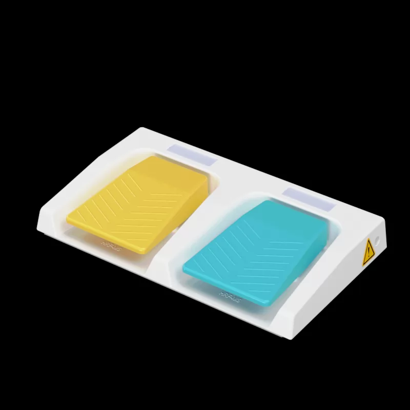
When it comes to choosing the right foot switch for your needs, understanding the differences between momentary and maintained foot switches is critical. Many users wonder about which type best suits their application, leading to common questions: "When should I use a momentary foot switch?" or "What scenarios require a maintained foot switch?" These questions often arise from pain points

September. 18, 2026

Ergonomic benefits of dual pedal design Ergonomic benefits of dual pedal design
In today’s fast-paced work environment, achieving ergonomic efficiency is more crucial than ever, especially for those who spend long hours at desks or in production lines. Users often face issues such as repetitive strain injuries and fatigue due to poorly designed tools. The dual pedal switch design addresses these pain points effectively, allowing users to operate machinery or software

September. 17, 2026

IP67 vs IP68 foot switch for marine use IP67 vs IP68 foot switch for marine use
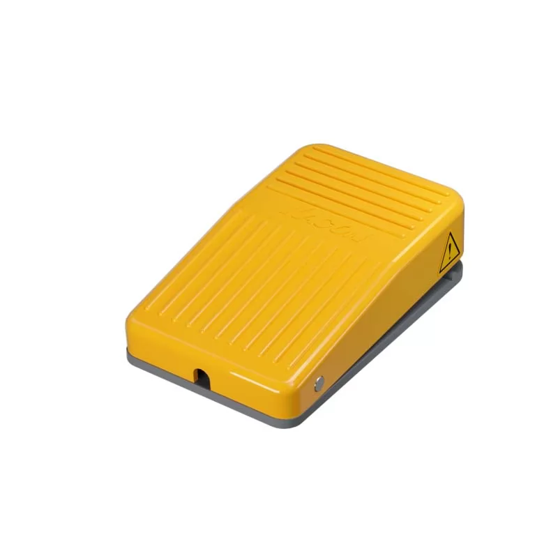
IP ratings, or Ingress Protection ratings, indicate how well a device is protected against dust and water. The ratings range from IP00 (no protection) to IP68 (protected against dust and water immersion).

September. 16, 2026

Best dual foot switch for hydraulic presses Best dual foot switch for hydraulic presses
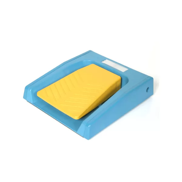
In today's rapidly evolving manufacturing environment, operators face numerous challenges when using hydraulic presses. Duplicate tasks, cramped workspace, and the need for efficient hands-free operation are common pain points. A dual foot switch is an effective solution for these issues, allowing for precise control with minimal user strain. By incorporating advanced functionality, these

September. 16, 2026

Wiring diagram for dual safety foot switches Wiring diagram for dual safety foot switches
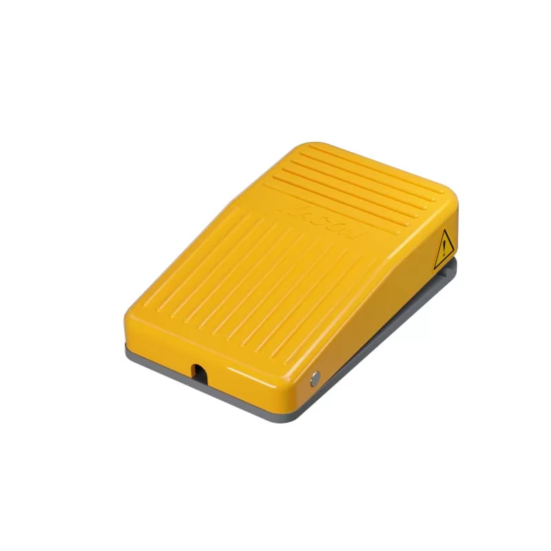
The dual foot pedal switch is an essential component in various industrial applications, providing remote control for machinery when combined with a safety mechanism. Proper wiring is crucial for ensuring safety and functionality. In this article, we will explore the wiring diagrams for dual safety foot switches, highlighting best practices, safety regulations, and practical steps for

September. 15, 2026

Troubleshooting 3-position switch contacts Troubleshooting 3-position switch contacts
Are you struggling with malfunctioning 3-position switches in your control systems? Many technicians and hobbyists experience issues related to inconsistent switch contacts that lead to operational failures. Here, we will explore effective troubleshooting strategies that not only enhance the reliability of your systems but also minimize downtime. By focusing on practical solutions grounded in

September. 15, 2026

Want to speak to us?
The quickest way to identify the best solution for your needs is to speak with one of our team of experts. We'll be able to quickly narrow down your options and give you objective advice on the best fit.
Get in Touch
  • Products
    • Medical Foot Switch
    • Heavy Duty Footswitch
    • Limit Switch
    • Control Switch
    • Safety Door Switch
    • Safety Relay Module
    • Safety Light Curtain
    • Relay
    • Terminal Block
    • Buzzer
    • Timer
    • Temperature Controller
    • Micro Switch
    • Circuit Protection
    • Tower Light
    • Power Supply
  • About KACON
    • Company Profile
    • Quality Certificates
    • Warranty Policy
  • Solution
    • Solution Proposal
    • Successful Cases
  • Quick Links

    • Customization
    • Download
    • Project Management
    • FAQ
    • Media
  • Send Inquiry
Copyright @ Zhejiang Kacon Electric Co., Ltd. All Rights Reserved | Sitemap | Powered by Reanod